Inside a high-voltage multiplier or rectifier stage, the diode usually sits in a series string where each part holds its share of the reverse voltage. This is an axial-leaded, fast-recovery high voltage diode rated for 16 kV in that role, with a 5 mA average forward current and an 80 nS recovery time. It is the smallest voltage class in the 2CL7 axial family — the 18 kV and 20 kV parts carry the same current, recovery and surge figures — so choosing it is a matter of matching the stack rather than accepting a different electrical behaviour.
The body is a molded epoxy cylinder with tinned axial leads and a marked cathode band. That format suits high-voltage boards that are assembled and inspected by hand: the leads bend to the hole pitch, the body stands off the board surface, and a failed part can be desoldered and replaced without reworking a pad. Assemblies in the field often show the lead junction dressed with insulating adhesive, and that is also how we suggest it be fitted.
Typical work for this part includes rectifier and multiplier stages in X-ray and dental imaging power supplies, non-destructive testing sets, DC high-voltage generators, high-voltage test transformers, and accelerator or radar supplies. Repair work is a large part of it too: equipment built around a 16 kV axial diode can often be returned to service with a like-for-like replacement, once the reverse voltage, current and lead arrangement have been checked against the failed part.
It is a small-current device by design. The 5 mA average forward current is the ceiling for continuous operation, so use it in bias, feedback, multiplier and low-current rectifier duty rather than in the main power path of a large supply. If your stage runs at hundreds of milliamps, this is not the right part; at a few milliamps with 16 kV across it, it is exactly the class it was built for.
| Model | Reverse voltage | Forward current | Recovery time | Surge current | Forward voltage |
|---|---|---|---|---|---|
| 2CL75 | 16 kV | 5 mA | 80 nS | 0.5 A | ≥41.0 V |
| 2CL76 | 18 kV | 5 mA | 80 nS | 0.5 A | ≥43.0 V |
| 2CL77 | 20 kV | 5 mA | 80 nS | 0.5 A | ≥43.0 V |
| 2CL82 | 30 kV | 5 mA | 80 nS | 0.5 A | ≥52.0 V |
Two rows, one reference condition. On the datasheet, Vrrm and Vrwm both read 16 kV, and both are measured at the same point: Ta = 25 °C, Ir = 2.0 µA, with VRM = VRRM. The match is deliberate. Vrrm is the repetitive peak reverse voltage — the level the diode blocks on every cycle of the reverse waveform, with no recovery interval in between. Vrwm is the peak working reverse voltage under normal service, the highest steady reverse stress your circuit applies. Quoting both against the same leakage current states that the part holds 16 kV continuously in the application, not only for an instant. What that guarantees, and what it does not. Because the working figure equals the repetitive peak, there is no hidden step-down between the rating and the voltage you may actually use: the full 16 kV is available as working voltage. What it does not give you is a one-off allowance above that. The only surge figure published for this part is forward surge current — 0.5 A for a 0.01 s half-sine at 50 Hz — and it says nothing about the reverse direction. Treat 16 kV as the ceiling for every reverse excursion, commutation spike and start-up transient the stage can produce. In a multiplier chain or a rectifier string, check the worst-case peak across each individual diode, not just the DC rail, before you fix the number of parts in series. Leakage is the anchor, temperature is the variable. The 16 kV is a blocking level defined at 2.0 µA, and that same 2.0 µA appears in the rated condition for both rows. Raise the junction to 100 °C and the leakage at the same full voltage climbs to 20.0 µA; the voltage rating itself does not move. That is the practical split when you qualify the part: blocking capability stays stable across the −55 °C to +150 °C ambient range, while the current it leaks has to be budgeted at the temperature your enclosure actually reaches. Read both rows whenever you cross-reference a part. Some data sheets quote Vrwm lower than Vrrm, which means the working voltage you can apply sits below the headline figure. Here both read 16 kV, so a 16 kV rail with normal ripple operates at the rated blocking level rather than a reduced one. If your circuit presents a reverse transient above 16 kV, or the axial high voltage diode you are replacing was rated differently on the two rows, send us the rail voltage and the reverse waveform and we will confirm whether this class fits or whether the 18 kV or 20 kV step in the same family leaves the margin your design needs.
| Parameter | Symbol | Test conditions | Value |
|---|---|---|---|
| Repetitive peak backward voltage | Vrrm | Ta = 25 °C, Ir = 2.0 µA | 16 kV |
| Peak working backward voltage | Vrwm | Ta = 25 °C, Ir = 2.0 µA | 16 kV |
| Average forward current | If(AV) | 50 Hz half-sine wave, resistive load, Tbreak = 50 °C | 5 mA |
| Backward recovery time | Trr | — | 80 nS |
| Surge forward current | Ifsm | 0.01 s, 50 Hz half-sine wave | 0.5 A |
| Forward peak voltage | Vfm | — | ≥41.0 V |
| Backward peak current at 25 °C | Irrm1 | VRM = VRRM | 2.0 µA |
| Backward peak current at 100 °C | Irrm2 | VRM = VRRM | 20.0 µA |
| Operating ambient temperature | Ta | — | −55 °C to +150 °C |
| Storage temperature | Tstg | — | −55 °C to +125 °C |
| Package | — | Molded epoxy, axial leads | Cylindrical axial-leaded body |
| Device type | — | — | Fast recovery high voltage diode |
The leakage figure decides more than the 16 kV headline. With the full reverse voltage applied, the part leaks 2.0 µA at 25 °C and 20.0 µA at 100 °C. That tenfold change is normal silicon behaviour as the junction warms, but it is the figure to design against, because leakage in a high-impedance multiplier node turns into offset and noise, and it also heats the junction a little further. High voltage diode manufacturers quote leakage at a stated voltage and temperature for exactly this reason: a 16 kV part quoted at 25 °C alone says little about how it behaves inside a warm enclosure.
Forward voltage is the second number worth reading twice. Vfm is published as ≥41.0 V at peak, which sounds large until you remember that the chip stack has to hold 16 kV in the opposite direction. At the 5 mA average rating the resulting dissipation sits in the region of 0.2 W — small in absolute terms, but concentrated in a molded cylinder with limited surface area, so check it against your thermal path rather than dismissing it because the current is small.
Reverse recovery is 80 nS. Where the diode rectifies a 50 Hz half-sine, recovery barely enters the picture; where the stage switches faster or the diode feeds short pulses, 80 nS is what stops it conducting in the reverse direction after the forward current has fallen.
The surge rating is 0.5 A for a 0.01 s half-sine pulse. That covers the charging current when a capacitor bank first fills and the transients a multiplier throws at the diode. It is a non-repetitive figure, so surges that arrive in quick succession accumulate stress even when each one on its own is inside the limit.
The temperature window runs from −55 °C to +150 °C ambient in operation, and from −55 °C to +125 °C in storage. Storage tops out lower than operation, which is worth remembering if parts are kept in a hot equipment bay or near a curing oven.
Selection starts with your circuit, not a catalogue number: tell us the working voltage, load current, switching frequency and ambient cooling conditions, and our engineers will match a model from our range and explain the margin left in the design. Each model ships with its datasheet, package drawing and installation guide, and we stay available for mounting and soldering questions, start-up checks and fault finding when an existing part runs hot or fails early. Orders run from about 7 days to 6 months depending on quantity, usually by international express.
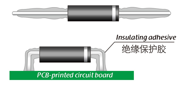
Here, suitable insulation adhesive materials can be selected based on the different usage situations of engineers.