• HV37-10F  Fast Recoveryhigh voltage diode 10KV, 350mA, 75nS
  • HV37-10F  Fast Recoveryhigh voltage diode 10KV, 350mA, 75nS
  • HV37-10F  Fast Recoveryhigh voltage diode 10KV, 350mA, 75nS
  • HV37-10F  Fast Recoveryhigh voltage diode 10KV, 350mA, 75nS
  • HV37-10F  Fast Recoveryhigh voltage diode 10KV, 350mA, 75nS
  • HV37-10F  Fast Recoveryhigh voltage diode 10KV, 350mA, 75nS

HV37-10F Fast Recoveryhigh voltage diode 10KV, 350mA, 75nS

No.HV37-10F
Products Main features:
1、Axial leaded connection.
2、High thermal conductivity epoxy compound molding.
3、Fast Reverse Recovery Time for High Efficiency.
4、Special passivation glue chip protection
5、Excellent discharge characteristics.
  • HV37-10F  Fast Recoveryhigh voltage diode 10KV, 350mA, 75nS
  • HV37-10F  Fast Recoveryhigh voltage diode 10KV, 350mA, 75nS
  • HV37-10F  Fast Recoveryhigh voltage diode 10KV, 350mA, 75nS
  • Desciption

  • data sheet

  • Package Size

  • Installation Guide

Product Overview

This high voltage diode is an axial-lead fast-recovery rectifier in the HV37 family, built in a cylindrical molded body with a marked cathode band. It is intended for through-hole mounting on high-voltage boards where a surface-mount package would be difficult to inspect, pot or replace. Typical duties include rectification and clamping in medical imaging power supplies, industrial NDT equipment, HVDC and high-voltage test sets, and radar or pulse circuits. Because the leads are axial, the body can sit above the board, be formed to the available space, and be surrounded by insulating adhesive or potting compound as part of the high-voltage isolation plan. Use it where the circuit needs a fast-recovery high voltage diode with a defined cathode end and straightforward inspection after soldering.

Industrial Durability

  • In industrial high voltage diodes, the wide operating range covers cold start-up, warm-up drift and enclosure heat, but it is still an ambient limit; local heating from nearby components must be added to the thermal calculation.
  • Thermal cycling is the usual life limiter: keep adhesive coverage even, avoid voids at the body, and let the assembly cool under the same controlled conditions on every cycle.
  • The molded body and axial leads can be inspected after soldering, so a cracked seal or a bent lead is visible before the board is potted.
  • For long-life equipment, recheck reverse leakage after potting and again after the first thermal cycle rather than relying only on the pre-assembly reading.
  • Store the parts in their original packaging in a dry place, and bring them to room temperature before soldering if they have been in a cold store; condensation on a high-voltage body is easier to prevent than to remove.
  • As high voltage diode manufacturers, we build the part around a through-hole axial package that can be inspected and reworked after soldering, with straight or bent leads to suit the board.
  • A high thermal conductivity epoxy body moves heat away from the chip instead of letting it collect at the junction.
  • A special passivation glue layer protects the chip surface, helping the blocking behavior stay stable after thermal cycling and repeated switching.
  • The construction is chosen for excellent discharge characteristics, so the diode can handle pulse and discharge duties as well as continuous rectification.
  • The cathode band is visible on the body, which lets the assembly team confirm polarity before soldering and again after cleaning.

Electrical Specifications

ParameterValue
Repetitive peak reverse voltage (Vrrm)10 kV at Ta = 25 °C, Ir = 2.0 µA
Average forward current, in air (If2(AV))350 mA at Ta = 40 °C
Average forward current, in oil (If2(AV))190 mA at Ta = 55 °C
Backward recovery time (Trr)75 ns
Surge forward current (Ifsm)15 A, 0.01 s half-sine wave, 50 Hz
Operating ambient temperature (Ta)-55 to +125 °C
Storage temperature (Tstg)-55 to +125 °C
Forward peak voltage (Vfm)≥16 V
Reverse leakage (Irrm1)2.0 µA at Ta = 25 °C, VRM = VRRM
Reverse leakage (Irrm2)10.0 µA at Ta = 100 °C, VRM = VRRM
PackageAxial-lead molded body with cathode band
Chip protectionSpecial passivation glue

Voltage Withstand and Insulation

In high voltage diodes, the practical limit is often the surface path around the package rather than the silicon itself, so the board layout has to keep creepage and clearance under control. Slot the board, add insulating barriers or use a potting compound when the spacing is tight, and keep solder joints and component edges smooth; a point or a void can start a discharge path even when the nominal spacing looks adequate.

High-Frequency Circuit Performance

  • Keep the commutation loop short and the return path close to the diode; lead length and loop area add inductance that can swamp the benefit of a fast recovery time.
  • Treat the recovery time as a datasheet condition, not a guarantee for every layout, and verify the waveform on your own board at the current, voltage and temperature you will actually run.
  • Expect switching loss to rise with frequency and reverse voltage; a current level that is comfortable at low frequency may need to be derated once the diode is switching hard.
  • Use the axial leads to position the body away from heat-sensitive parts, but do not use long leads as a substitute for proper spacing on a high-voltage board.
  • Check ringing and reverse-recovery overshoot at start-up and at maximum load, because those conditions often expose a layout issue before steady state does. Recovery time is where this part earns its place in a switching design. In a high voltage diode, that behavior is useful in rectifiers fed by high-frequency inverters, in pulse circuits with fast edges, and in boards where a slower rectifier would force a larger snubber or a lower switching frequency. The construction supports that electrical behavior: the chip is sealed in a molded body, and the axial leads give a mechanical joint that can be inspected after assembly. The result is a part intended for repeated commutation rather than a single, gentle operating point.

Current Handling and Thermal Derating

  • If the diode runs close to the current limit, shorten the leads where possible, increase copper area around the joints, and keep the body out of still-air pockets. - For oil-immersed assemblies, confirm that the oil, seals and any conformal coating are compatible with the diode body and the insulating adhesive you intend to use. Efficiency in a high voltage diode is usually a thermal problem before it is an electrical one. The fast recovery behavior reduces the switching component of the loss, but it does not remove conduction loss, and it does not make a marginal thermal design safe. A useful approach is to measure body temperature on the first prototype, compare it with the ambient you used for the current rating, and then decide whether the board needs more copper or airflow. If the diode is part of a high-frequency stage, check efficiency at both light load and full load; the light-load behavior often shows whether recovery and leakage are behaving as expected.

Package Fit and Installation Guide

  1. Compare the package size drawing with the PCB holes, keep-out area and creepage path; do not force an axial-lead body into a footprint designed for a surface-mount diode.
  2. Form the leads with support at the body, not at the seal, and keep the bend radius smooth if you need a bent-lead version.
  3. Insert the diode with the cathode band on the cathode side of the circuit, and mark the orientation on the board or in the assembly photo for inspection.
  4. Set the body height and spacing so the high-voltage path has the clearance your insulation plan requires, then solder the joints with a controlled iron or wave process and clean flux residue.
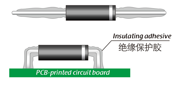
  5. Apply the chosen insulating adhesive or potting compound around the body and leads where the assembly calls for it, and cure it according to the adhesive supplier's instructions.
  6. Inspect the solder fillets, polarity, adhesive coverage and clearance before the board goes to test; a high-voltage diode can pass a quick continuity check and still fail on a hi-pot test because of a sharp edge or a void.
  7. Silicone cures to a transparent, elastic rubber with good shock resistance and can handle severe stress from large high-to-low temperature swings, roughly -40 to 200 °C; it is a sensible choice where thermal expansion and mechanical movement are the main concerns.
  8. Acrylic cures to a transparent, hard coating with low moisture absorption, fast cure and good wear and insulation properties; it suits assemblies where a hard, clean surface is wanted and the process can tolerate a fast cure.
  9. Urethane cures to a transparent, hard coating with strong wear and moisture resistance and stable low-temperature behavior, but it is less resistant to high temperature; use it where low-temperature stability and abrasion resistance matter more than heat.
  10. Epoxy is very sturdy, usually opaque, and offers good moisture, chemical and wear resistance together with good dielectric properties; it is the choice for a robust, fully sealed assembly where inspection of the chip is not required.
  11. Oil or insulating-gas immersion is the preferred environment for many high voltage diodes, while secondary packaging and exposed-air use with air cooling place higher demands on heat dissipation and field control; for exposed-air mounting, fit insulated electrodes at both ends and keep the surface clean and dry.

HV37 Voltage & Current Ladder

  • HV37-06F — 6 kV repetitive peak reverse voltage (Vrrm), 500 mA average forward current in air at 40 °C and 300 mA in oil at 55 °C; the highest current option in the family, so start here when the reverse voltage is modest and the load current is the harder limit.
  • HV37-08F — 8 kV Vrrm, 400 mA in air at 40 °C and 210 mA in oil at 55 °C; a middle step for designs that need one voltage class more than the 6 kV part but still want useful current headroom.
  • HV37-15F — 15 kV Vrrm, 250 mA in air at 40 °C and 150 mA in oil at 55 °C; the top of the family, for the highest reverse voltage requirement, with the least current headroom.
  • If your worst-case reverse peak sits between two models, compare the actual ambient and cooling method, not just the headline current: the in-oil rating uses a 55 °C reference, while the in-air rating uses 40 °C, so the two figures answer different thermal questions.

Ordering & Delivery

Because we are high voltage diode manufacturers, we confirm quantity, destination and required date against your quotation before production is scheduled. Shipments are arranged by international express; packing, lead time and payment terms are confirmed with the order because they depend on quantity and destination. The datasheet, package size drawing and installation guide can be supplied for design review. If you are matching an existing part, send the marking and the operating conditions so we can check the electrical fit before you commit. We supply this rectifier for prototype builds, production batches and replacement requirements, and we will tell you when a different voltage class or current rating is the better match for the circuit.

Technical Support & Model Matching

Selection starts with your circuit, not a catalogue number: tell us the working voltage, load current, switching frequency and ambient cooling conditions, and our engineers will match a model from our range and explain the margin left in the design. Each model ships with its datasheet, package drawing and installation guide, and we stay available for mounting and soldering questions, start-up checks and fault finding when an existing part runs hot or fails early. Orders run from about 7 days to 6 months depending on quantity, usually by international express.

FAQ

Can this diode replace an existing axial high-voltage rectifier?

Compare four things before you substitute it: repetitive peak reverse voltage, average forward current at your cooling condition, recovery time, and the axial package drawing. If the existing part is an axial rectifier with the same cathode orientation and the board has room for the lead form, this part is a candidate. Send us the marking and the circuit conditions so we can check the electrical fit rather than relying on the model name alone.

Does the 10 kV reverse-voltage rating hold at elevated temperature?

The 10 kV figure is the repetitive peak reverse voltage at 25 °C. Reverse leakage rises at 100 °C, so check the design margin at the hot end of the operating range, not only at room temperature. Use the worst-case reverse peak and the actual ambient in your calculation, including start-up and load-dump events.

Is the diode suitable for pulse discharge circuits?

Yes. The construction is chosen for excellent discharge characteristics as well as continuous rectification, so it can be used in pulse and discharge duties within its voltage and current ratings. For a repetitive pulse design, confirm the pulse width, repetition rate and thermal conditions against the datasheet before you finalize the circuit.

What documents can I review before design approval?

The electrical datasheet, package size drawing and installation guide are available. They cover the absolute maximum ratings, the test conditions behind the current and voltage figures, the axial package dimensions, and the recommended mounting and insulation practice.

How is this part tested before shipment?

As high voltage diode manufacturers, we screen production units for blocking voltage, reverse leakage and recovery time, and the test bench covers high-voltage and high-temperature bias checks. The aim is to catch a batch issue before the diode reaches your line. If you need a specific test record for your quality file, ask our team what is available with the order.

How do the voltage classes in this family differ?

Within the same axial family, a higher repetitive peak reverse voltage gives more margin for the blocking side, while the current headroom steps down as the voltage class rises. Pick the lowest voltage class that still covers your worst-case reverse peak with the margin your design rules require, then check the forward current at your actual ambient and cooling method. If you are between two classes, send us the waveform and thermal conditions and we will compare them against the datasheet.

The selection of high-voltage diodes is closely related to their usage environment。

1. Used in insulating oil. (Recommended)
2. Used in insulating gases. (Recommended)
3. Secondary packaging use. (High requirements for heat dissipation and other parameter performance of components)
4. Use in exposed air or add air cooling. (If the size of the high-voltage diode is small, it is easy to discharge, and the heat dissipation performance is average.)

For high-voltage diodes used in exposed air, it is recommended to install them with insulated electrodes at both ends.


Common treatment methods for surface adhesive insulation:

Characteristics of insulation adhesive material:

1. Silicone material usually presents a transparent and elastic rubber state after curing, which is more effective in shock resistance and can also withstand severe stress changes caused by large high and low temperature changes (-40 ° C~200 ° C).

2. Acrylic materials typically exhibit a transparent and hard coating after curing, with low moisture absorption and fast curing time, as well as excellent wear resistance and insulation.

3. After curing, Urethane material usually presents a transparent and hard coating, which has superior wear resistance and good moisture resistance. Its performance is particularly stable in low temperature environments, but it is less resistant to high temperatures.

4. The coating material based on epoxy is very sturdy and usually opaque, with good moisture and moisture resistance. Its resistance to chemical corrosion and wear is also very good. In addition, epoxy also has good dielectric properties.

Here, suitable insulation adhesive materials can be selected based on the different usage situations of engineers.

HVDIODE - Suly Electronics Co., Ltd.

Expects To Provide You With Perfect Service

Name
Email *
Verification Code *
Click to verify
Leave a message
Name
Email *
Message
Verification Code *
Click to verify
We use Cookie to improve your online experience. By continuing browsing this website, we assume you agree our use of Cookie.