• HV37-12F  Fast Recoveryhigh voltage diode 12KV, 300mA, 75nS
  • HV37-12F  Fast Recoveryhigh voltage diode 12KV, 300mA, 75nS
  • HV37-12F  Fast Recoveryhigh voltage diode 12KV, 300mA, 75nS
  • HV37-12F  Fast Recoveryhigh voltage diode 12KV, 300mA, 75nS
  • HV37-12F  Fast Recoveryhigh voltage diode 12KV, 300mA, 75nS
  • HV37-12F  Fast Recoveryhigh voltage diode 12KV, 300mA, 75nS

HV37-12F Fast Recoveryhigh voltage diode 12KV, 300mA, 75nS

No.HV37-12F
Products Main features:
1、Axial leaded connection.
2、High thermal conductivity epoxy compound molding.
3、Fast Reverse Recovery Time for High Efficiency.
4、Special passivation glue chip protection
5、Excellent discharge characteristics.
  • HV37-12F  Fast Recoveryhigh voltage diode 12KV, 300mA, 75nS
  • HV37-12F  Fast Recoveryhigh voltage diode 12KV, 300mA, 75nS
  • HV37-12F  Fast Recoveryhigh voltage diode 12KV, 300mA, 75nS
  • Desciption

  • data sheet

  • Package Size

  • Installation Guide

Product Overview

HV37-12F is an axial-leaded fast recovery rectifier diode built for high-frequency rectification in high-voltage power supplies. The axial package has a black epoxy body, a white cathode band and straight leads, and the construction uses a high thermal conductivity epoxy compound with special passivation glue chip protection. That combination supports stable voltage control and clean discharge behaviour in compact, high-impedance circuits. It suits designs that need headroom for transients, insulation coordination and high-voltage hold-off, but do not need the top voltage of the family. Typical use is on a PCB or inside an insulated assembly where the diode rectifies a high-frequency high-voltage rail in medical imaging, industrial NDT, HVDC, high-voltage test or radar power equipment. - Fast turn-off for high-frequency rails: The diode is designed around a fast recovery characteristic, so it returns to the blocking state quickly after conduction. In a high-frequency rectifier this shortens the window where reverse current flows and helps reduce switching loss. - Efficiency where timing matters: High voltage diodes in the HV37 family are used in circuits where a slow rectifier would blur the switching waveform. The fast recovery behaviour keeps the rectified output cleaner and lowers the heat that comes from repeated turn-off losses. - Stable high-voltage blocking: The passivation glue chip protection and high thermal conductivity epoxy molding support the chip surface and help the body handle voltage stress without giving up mechanical strength. - Discharge behaviour: The construction is chosen for excellent discharge characteristics, which matters in high-impedance high-voltage paths where stray charge and surface effects can disturb clean switching. - Reliability under demanding duty: The part is built for repeated high-voltage switching rather than one-off conduction. Its axial body and encapsulated chip are intended to keep performance consistent through thermal cycling and long operating periods. - A practical fit for compact assemblies: The axial format allows point-to-point mounting on a PCB or inside an insulated module, and the white cathode band gives a clear polarity reference during assembly and inspection.

Key Specifications

ParameterSymbolTest conditionValue
Repetitive peak backward voltageVrrmTa = 25 °C, Ir = 2.0 µA12 kV
Average forward current in airIf2(AV)Ta = 40 °C, in air300 mA
Average forward current in oilIf2(AV)Ta = 55 °C, in oil170 mA
Backward recovery timeTrr—75 ns
Surge forward currentIfsm0.01 s, half-sine wave, 50 Hz15 A
Operating ambient temperatureTa—-55 to +125 °C
Storage temperatureTstg—-55 to +125 °C
Forward peak voltageVfm—≥19 V
Reverse leakage at 25 °CIrrm1VRM = VRRM2.0 µA
Reverse leakage at 100 °CIrrm2VRM = VRRM10.0 µA

Model & Series Reference

The HV37 family steps through 6 kV, 8 kV, 10 kV, 12 kV and 15 kV fast recovery parts, with current capability falling as the voltage rating rises. The 12 kV model is the middle-high step: it gives more margin than the 10 kV part for transients and insulation coordination, while keeping a higher current rating than the 15 kV version. That makes it a sensible choice when a 10 kV design is running close to its voltage limit but a 15 kV part would add cost or reduce current headroom. As high voltage diode manufacturers, we keep the model marking and datasheet conditions tied to the part number, so replacement should start from the number printed on the original body. Do not substitute a lower Vrrm part into a 12 kV position, and do not assume that a higher-voltage part will carry the same current. If you are moving a design from 10 kV to 12 kV, recheck the forward current, the cooling method and the package drawing rather than changing only the voltage field. For an existing assembly, send a photo of the marking and the lead form if you need a like-for-like check.

Thermal & Current Derating

For this high voltage diode, the two current figures in the datasheet are not interchangeable. One is stated for 40 °C air, the other for 55 °C oil, so the lower oil figure is tied to a hotter test ambient and a different cooling medium rather than to a weaker part. Design against the line that matches how the diode will actually be cooled. If the assembly runs in still air inside a closed enclosure, the air figure is the closer starting point, but nearby resistors, transformers and board density can push the local temperature above the stated ambient. In oil or insulating gas, the medium helps with insulation and heat transfer, but the oil test condition still sets the reference current. At the upper end, leave margin for self-heating and for the temperature rise of the surrounding assembly; a diode that is comfortable on the bench may run much hotter inside a sealed high-voltage compartment. The high thermal conductivity epoxy compound is there to move heat from the chip toward the body and leads, but it does not replace a thermal path. Clamp or mount the leads so heat can leave the body, avoid long unsupported runs, and check the actual lead and body temperature after the unit has reached steady state. If your load is continuous, or if the ambient is not well controlled, confirm the derating with our engineers before you commit the design.

Package Dimensions

Package codeHVD-415
Body diameter (D)⌀4.5 mm / 0.177 in
Body length (L1)15 mm / 0.591 in
Lead diameter (d)⌀0.8 mm / 0.031 in
Lead length (L2)25 mm / 0.98 in
Tolerance±0.2 mm / 0.01 in, except L2 ±0.5 mm / 0.02 in
Cathode markingWhite band at cathode end
Mounting styleAxial leads, straight

Installation & Mounting

  1. Decide the cooling and insulation method before mounting. Insulating oil or insulating gas are the preferred environments for high voltage diodes in continuous service. If the diode must run in exposed air, plan air cooling and use insulated electrodes at both ends; a small body can otherwise discharge across the surface and its heat dissipation is only average. If it is enclosed in a secondary package or potting compound, check heat dissipation and the surrounding material before you seal it.
  2. Check polarity and part marking against the drawing. Confirm the printed model and the package code before forming or soldering the leads.
  3. Form the leads with support between the bend and the body. Keep the bend away from the epoxy seal, and do not pull on the lead while holding the body.
  4. Keep high-voltage spacing around the body and leads. Clean flux and contamination from the surface after soldering; surface leakage paths are more critical at high voltage than at low voltage.
  5. Solder with a controlled iron or reflow profile, and avoid overheating the axial seal. Let the part cool naturally before handling or applying insulation.
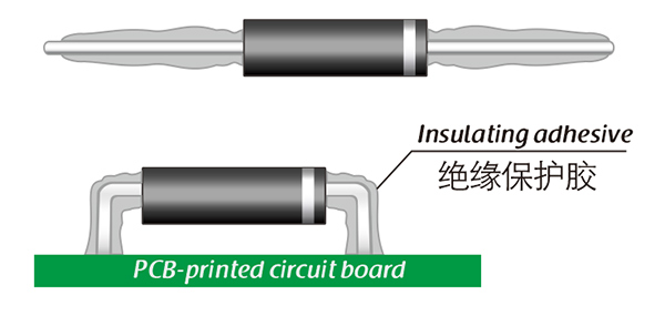
  6. Apply insulation adhesive only after the joint is clean and dry.
  7. Commission at partial voltage first. Check reverse leakage, waveform, body temperature and lead temperature before raising to the working level, then record the batch and test conditions for the next build.

Insulation Adhesive Options

  • Silicone: After curing, silicone usually stays transparent and rubbery. It absorbs shock and mechanical stress, and it copes with the expansion and contraction caused by wide temperature swings from -40 °C to 200 °C. It is a common choice where vibration or thermal cycling is a concern.
  • Acrylic: Acrylic adhesives normally cure to a transparent, hard coating with low moisture absorption and a fast cure. They add wear resistance and electrical insulation, which suits assemblies that need a firm surface and a short process time.
  • Urethane: Urethane typically cures to a transparent, hard coating with good wear and moisture resistance. It remains stable at low temperature, but it is less tolerant of high temperature than silicone, so check the hot end of your process.
  • Epoxy: Epoxy-based coating is very sturdy and usually opaque. It offers good resistance to moisture, chemicals and wear, and it has useful dielectric properties. It is a good fit where mechanical protection and environmental sealing matter more than a transparent inspection window.
  • Selection note: Match the adhesive to the mounting method, the voltage stress, the cure process and the temperature cycle the assembly will see. If the diode sits in oil or gas, the adhesive mainly supports the chip and lead area; in exposed air, it also helps control surface leakage and discharge.

Ordering & Delivery

  • Shipping: International express.
  • Quantity and lead time: Minimum order quantity and current lead time depend on the model, quantity and production schedule; confirm both with your sales contact before the order is released.
  • Quotation details: Send the part number, quantity, required lead form and any insulation adhesive preference so the quotation matches what you will build.
  • Payment and trade terms: Payment method, Incoterms and other terms are stated on the quotation and proforma invoice; ask for the version that applies to your order.
  • Packing: Packing is agreed with your sales contact before dispatch so the axial leads arrive straight and the body is protected in transit.
  • Samples: Ask your sales contact about sample availability and the current sample schedule if you need a unit for evaluation.
  • Technical file: The datasheet, package drawing and installation guide are available for your review before you finalise the assembly.
  • Service: As high voltage diode manufacturers, we support model matching, datasheet questions and replacement checks; tell us if the part is for an existing assembly or a new build.

Technical Support & Model Matching

Selection starts with your circuit, not a catalogue number: tell us the working voltage, load current, switching frequency and ambient cooling conditions, and our engineers will match a model from our range and explain the margin left in the design. Each model ships with its datasheet, package drawing and installation guide, and we stay available for mounting and soldering questions, start-up checks and fault finding when an existing part runs hot or fails early. Orders run from about 7 days to 6 months depending on quantity, usually by international express.

FAQ

Can two diodes be connected in series for a higher blocking voltage?

High voltage diodes can be connected in series in high-voltage assemblies, but the string has to share reverse voltage evenly. Leakage current, grading resistors or networks, creepage distance and the insulation medium all affect sharing. If you plan a series stack, send the circuit details so the string can be checked as a system rather than treating each diode as a standalone part.

What should I check when the diode arrives?

Check the printed model and cathode band, inspect the epoxy body for cracks or chips, confirm the leads are straight, and compare the package dimensions with the drawing. If the parts are going into a high-voltage assembly, keep them in their protective packaging until soldering and avoid touching the lead seal.

How does reverse leakage change with temperature?

The datasheet gives 2.0 µA at 25 °C and 10.0 µA at 100 °C with VRM at the rated VRRM. Leakage rises with temperature, so a circuit that depends on very low reverse current should be checked hot, not only at room temperature.

What is the difference between the repetitive peak rating and a working voltage?

For this high voltage diode, the repetitive peak backward voltage is a maximum repeated blocking level, not a recommended continuous operating point. Design your working rail below it with margin for transients, switching overshoot and insulation tolerance. The exact margin depends on the circuit and the environment.

What is the difference between forward peak voltage and repetitive peak backward voltage?

Forward peak voltage is the maximum voltage drop you allow across the diode while it conducts; the datasheet gives a value of at least 19 V for this model. Repetitive peak backward voltage is the blocking rating in the reverse direction. The two numbers describe different operating states, so do not compare them directly.

Does this diode need a heatsink?

There is no separate heatsink in the axial package; heat leaves through the leads and body into the surrounding medium. In air, use short, supported leads and avoid crowding; in oil or gas, the medium carries heat away. Check body and lead temperature at steady state before finalising the design.

How is this model checked before shipment?

The production test floor includes high-voltage test benches, high-temperature and voltage-bias test benches, high and low temperature chambers, leakage current testers, TRR testers and surge impact benches. For a qualification file, ask for the test record that applies to your batch and compare it with the datasheet conditions. The model marking, package dimensions and cathode band are also checked before packing.

The selection of high-voltage diodes is closely related to their usage environment。

1. Used in insulating oil. (Recommended)
2. Used in insulating gases. (Recommended)
3. Secondary packaging use. (High requirements for heat dissipation and other parameter performance of components)
4. Use in exposed air or add air cooling. (If the size of the high-voltage diode is small, it is easy to discharge, and the heat dissipation performance is average.)

For high-voltage diodes used in exposed air, it is recommended to install them with insulated electrodes at both ends.


Common treatment methods for surface adhesive insulation:

Characteristics of insulation adhesive material:

1. Silicone material usually presents a transparent and elastic rubber state after curing, which is more effective in shock resistance and can also withstand severe stress changes caused by large high and low temperature changes (-40 ° C~200 ° C).

2. Acrylic materials typically exhibit a transparent and hard coating after curing, with low moisture absorption and fast curing time, as well as excellent wear resistance and insulation.

3. After curing, Urethane material usually presents a transparent and hard coating, which has superior wear resistance and good moisture resistance. Its performance is particularly stable in low temperature environments, but it is less resistant to high temperatures.

4. The coating material based on epoxy is very sturdy and usually opaque, with good moisture and moisture resistance. Its resistance to chemical corrosion and wear is also very good. In addition, epoxy also has good dielectric properties.

Here, suitable insulation adhesive materials can be selected based on the different usage situations of engineers.

HVDIODE - Suly Electronics Co., Ltd.

Expects To Provide You With Perfect Service

Name
Email *
Verification Code *
Click to verify
Leave a message
Name
Email *
Message
Verification Code *
Click to verify
We use Cookie to improve your online experience. By continuing browsing this website, we assume you agree our use of Cookie.