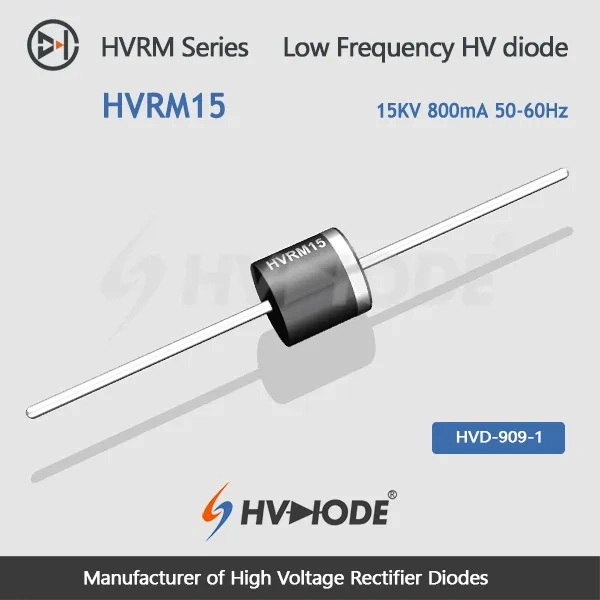
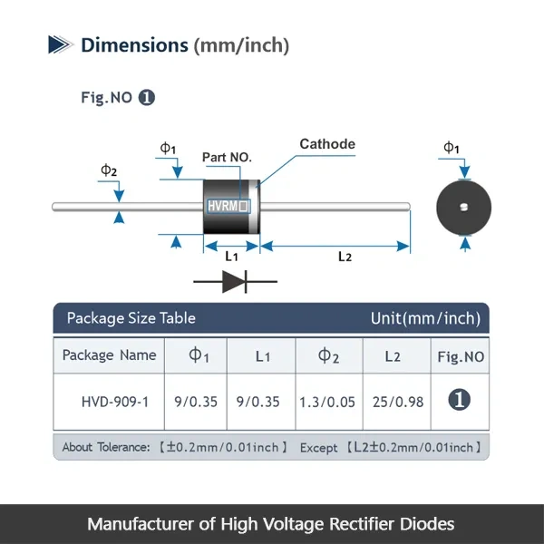
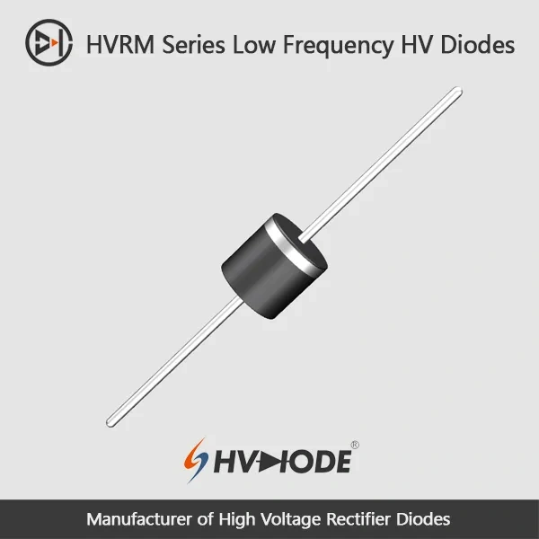
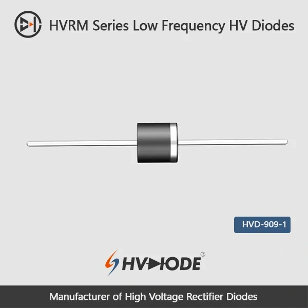
• HVRM15- Low frequency high voltage diode 15KV,0.8A,50-60Hz
  • HVRM15- Low frequency high voltage diode 15KV,0.8A,50-60Hz
  • HVRM15- Low frequency high voltage diode 15KV,0.8A,50-60Hz
  • HVRM15- Low frequency high voltage diode 15KV,0.8A,50-60Hz
  • HVRM15- Low frequency high voltage diode 15KV,0.8A,50-60Hz
  • HVRM15- Low frequency high voltage diode 15KV,0.8A,50-60Hz
  • HVRM15- Low frequency high voltage diode 15KV,0.8A,50-60Hz
  • HVRM15- Low frequency high voltage diode 15KV,0.8A,50-60Hz

HVRM15- Low frequency high voltage diode 15KV,0.8A,50-60Hz

No.HVRM15
Products Main features:
1、Axial leaded connection.
2、High thermal conductivity epoxy compound molding.
3、Excellent surge current resistance
4、Special high temperature resistant chip
  • HVRM15- Low frequency high voltage diode 15KV,0.8A,50-60Hz
  • HVRM15- Low frequency high voltage diode 15KV,0.8A,50-60Hz
  • HVRM15- Low frequency high voltage diode 15KV,0.8A,50-60Hz
  • HVRM15- Low frequency high voltage diode 15KV,0.8A,50-60Hz
  • Desciption

  • data sheet

  • Installation Guide

 HVRM15  Low frequency high voltage diode Data Sheet 
 Parameter Symbol Unit Test Conditions Value
 Repetitive Peak Backward Voltage Vrrm KV Ta=25℃  Ir=2.0μA 15
 Peak Working Backward Voltage Vrwm KV Ta=25℃  Ir=2.0μA 15
 Average Forward Current If(AV) A 50Hz Half-sine Wave , Resistance load @Tbreak=50℃ 0.8
 Backward Recovery Time Trr nS   --
 Surge Forward Current Ifsm A 0.01S @ Half-Sine wave  50Hz 80
 Operating Ambient Temperature Ta ℃   -55~+175
 Storage Temperature Tstg ℃   -55~+150
 Forward Peak Voltage Vfm V   ≥18.0
 Backward Peak  Current Irrm1 μA @ Ta=25℃ VRM=VRRM 2.0
Irrm2 μA @ Ta=100℃ VRM=VRRM 20.0
 Absolute Maximum Ratings & Electrical Characteristics


Key Features

  • Axial leaded connection — Through-hole leads seat in plated holes on rectifier boards and are straightforward to rework, which suits repair and replacement work as well as new builds.
  • High thermal conductivity epoxy molding — The molded body draws heat out of the chip and seals the pellet, so the part behaves consistently through the thermal cycling of a mains-frequency rectifier.
  • Excellent surge current resistance — The 80 A surge rating covers the inrush and fault transients that appear when a high-voltage stage charges a capacitor bank or a load shorts out.
  • Special high temperature resistant chip — Chosen for installations where the diode's own neighbourhood runs hot, so the part keeps working the same way after hours of operation rather than drifting as the enclosure warms.
  • A range that scales with your design — Our low frequency high voltage diodes cover 5 kV to 15 kV and 0.8 A to 2 A, so you can keep one supplier and one assembly method as your specifications change.

Mounting & Insulation Environment

Where the diode sits does much to decide how well a 15 kV part survives. Immersion in insulating oil is the strongest arrangement and the one we suggest first: the oil surrounds the body, holds back surface discharge and carries heat away from the chip. A sealed insulating gas atmosphere is the next preferred option and is common inside pressurised high-voltage enclosures. If the diode is wrapped or potted as a secondary package, thermal design becomes the limiting factor — the assembly around the diode, rather than the diode alone, sets how much current you can run. In exposed air a small high-voltage body can discharge across its own surface and heat rejection is only average, so fit insulated electrodes at both ends and add forced air where the layout allows. Tell us which environment applies and we will match the coating and the mounting advice to it.

Applications

  • Mains-frequency bridge rectifier boards — Rectifier legs that must block 15 kV in 50-60Hz equipment, sharing the board with several high voltage diodes.
  • Diode PCB assemblies — Through-hole positions on rectifier boards, including builds handled by contract assembly houses that need a documented part with a stable footprint.
  • High-voltage rectifier stacks and assemblies — Oil-filled or gas-filled rectifier assemblies where diodes are stacked to reach a higher working voltage.
  • Replacement in existing rectifier equipment — Servicing a failed 15 kV diode in a unit already in the field, where matching blocking voltage, current and lead form keeps the repair simple.
  • Prototype and laboratory builds — Benches that need a documented part to validate a high-voltage rectifier circuit before it moves to production.

Technical Support & Model Matching

Selection support starts before you order. Our technical team reviews your working voltage, forward current, surge and thermal conditions against the published datasheets, then recommends the closest high-voltage diode and confirms the matching part number. We also guide you through installation and insulation considerations, and help troubleshoot issues during qualification or after delivery. Suly Electronics manufactures these diodes directly, supplies them in bulk, and keeps answering technical questions for the parts you already use.

FAQ

Q1. How does this 15 kV diode differ from the other HVRM models?

This is the top of the range: 15 kV blocking with the lowest current rating, 0.8 A average forward current and 80 A surge handling. Lower-voltage members of the family carry more current — up to 2 A at 5 kV and 6 kV — so the choice usually comes down to whether your stage needs maximum standoff or more current. All of them are low frequency high voltage diodes built for 50-60Hz rectification.

Q2. Can I use it in a 50-60Hz bridge rectifier?

Yes. The average forward current is rated on a 50 Hz half-sine wave with a resistive load, which is the duty a bridge rectifier leg sees. Keep in mind that this is a low frequency rectifier and is not intended for high-frequency switching stages, so if your circuit switches well above mains frequency, ask us about a fast recovery part instead.

Q3. What does the 18.0 V forward peak voltage mean for my design?

Vfm is specified as ≥18.0 V, so budget for a forward drop of that order across the diode while it is conducting. That drop becomes heat inside the body, which is why the mounting medium matters as much as the diode itself: oil or a potted assembly carries the heat away, while open-air mounting needs more care. Build the layout around that drop rather than assuming a low forward voltage.

Q4. Is this a leaded part or a surface-mount part?

This model uses an axial leaded connection, so it mounts through holes on a rectifier board. Other diodes in the HVRM family use gullwing surface-mount leads, so if your board is laid out for a surface-mount foot, send the footprint and we will confirm which version fits. Lead form is worth checking early, because it is the one detail that cannot be adjusted after the board is made.

Q5. Can it replace a 15 kV diode from another supplier?

Usually, if the ratings and the lead form line up: compare repetitive peak reverse voltage, average forward current, surge current and the physical lead arrangement against your existing part. We are high voltage diode manufacturers, so we can look at the part number you are running and tell you whether this 15 kV model matches it, or whether another member of the range is a closer fit.

Q6. Do the ratings still hold when the diode runs hot?

The electrical characteristics are quoted at 25 °C, and reverse leakage current rises as temperature climbs, so thermal design is part of the electrical design at this voltage. The chip is built for a wide ambient range and the epoxy molding moves heat away from the junction. In an enclosure or an oil tank, keep the mounting surface and the surrounding medium doing their share of the work.
The selection of high-voltage diodes is closely related to their usage environment。

1. Used in insulating oil. (Recommended)
2. Used in insulating gases. (Recommended)
3. Secondary packaging use. (High requirements for heat dissipation and other parameter performance of components)
4. Use in exposed air or add air cooling. (If the size of the high-voltage diode is small, it is easy to discharge, and the heat dissipation performance is average.)

For high-voltage diodes used in exposed air, it is recommended to install them with insulated electrodes at both ends.


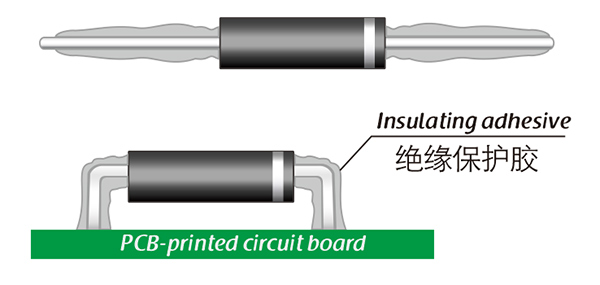
Common treatment methods for surface adhesive insulation:

Characteristics of insulation adhesive material:

1. Silicone material usually presents a transparent and elastic rubber state after curing, which is more effective in shock resistance and can also withstand severe stress changes caused by large high and low temperature changes (-40 ° C~200 ° C).

2. Acrylic materials typically exhibit a transparent and hard coating after curing, with low moisture absorption and fast curing time, as well as excellent wear resistance and insulation.

3. After curing, Urethane material usually presents a transparent and hard coating, which has superior wear resistance and good moisture resistance. Its performance is particularly stable in low temperature environments, but it is less resistant to high temperatures.

4. The coating material based on epoxy is very sturdy and usually opaque, with good moisture and moisture resistance. Its resistance to chemical corrosion and wear is also very good. In addition, epoxy also has good dielectric properties.

Here, suitable insulation adhesive materials can be selected based on the different usage situations of engineers.

HVDIODE - Suly Electronics Co., Ltd.

Expects To Provide You With Perfect Service

Name
Email *
Verification Code *
Verification Code
Leave a message
Name
Email *
Message
Verification Code *
Verification Code
We use Cookie to improve your online experience. By continuing browsing this website, we assume you agree our use of Cookie.