| HVRM5 Low frequency high voltage diode Data Sheet | ||||
| Parameter | Symbol | Unit | Test Conditions | Value |
| Repetitive Peak Backward Voltage | Vrrm | KV | Ta=25℃ Ir=2.0μA | 5 |
| Peak Working Backward Voltage | Vrwm | KV | Ta=25℃ Ir=2.0μA | 5 |
| Average Forward Current | If(AV) | A | 50Hz Half-sine Wave , Resistance load @Tbreak=50℃ | 2 |
| Backward Recovery Time | Trr | nS | -- | |
| Surge Forward Current | Ifsm | A | 0.01S @ Half-Sine wave 50Hz | 180 |
| Operating Ambient Temperature | Ta | ℃ | -55~+175 | |
| Storage Temperature | Tstg | ℃ | -55~+150 | |
| Forward Peak Voltage | Vfm | V | ≥6.0 | |
| Backward Peak Current | Irrm1 | μA | @ Ta=25℃ VRM=VRRM | 2.0 |
| Irrm2 | μA | @ Ta=100℃ VRM=VRRM | 20.0 | |
| Absolute Maximum Ratings & Electrical Characteristics | ||||
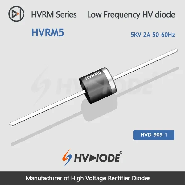
HVRM5 is the lowest-blocking member of the HVRM power-frequency line, and it carries the highest average current that line offers. Reverse blocking appears twice in the data — 5 kV repetitive peak (Vrrm) and 5 kV peak working (Vrwm), both measured at Ta = 25 °C with 2.0 µA of reverse current — while the forward side is rated 2 A average on a 50 Hz half-sine wave into a resistive load at Tbreak = 50 °C. Forward peak voltage is specified at ≥6.0 V, the lowest figure in the range, so every ampere of rectified current is bought with less forward drop than a higher-voltage build requires. This high voltage diode is a continuous-duty part for mains-frequency rectification, where the working peak stays under 5 kV and the average current stays at or below 2 A.
Three limits define the part. Reverse recovery time is not specified for it: at 50-60 Hz the diode is either conducting or blocking for most of the cycle, and a design that switches in the kilohertz range belongs with a fast-recovery or ultra-fast-recovery type instead. Average forward current stops at 2 A, so a heavier load calls for a different device rather than a hotter-running one. Blocking stops at 5 kV; above that the HVRM line continues up to 15 kV, and as high voltage diode manufacturers we supply the higher-voltage steps as well. Two practical notes: storage is rated -55 °C to +150 °C, narrower at the top than the operating range, and the 180 A figure describes a 0.01 s half-sine current pulse rather than a sustained overload.
Yes — 2 A is an average forward current rating, not a peak figure. It is measured on a 50 Hz half-sine wave into a resistive load at Tbreak = 50 °C, so the cooling your mounting provides decides how close you can sit to it. In insulating oil or a well-ventilated enclosure, running near 2 A is reasonable; inside a sealed or potted assembly the same current runs hotter, so keep margin or improve the heat path. Operating ambient is rated to +175 °C, and that is where the thermal budget ends.
It roughly multiplies by ten between 25 °C and 100 °C: 2.0 µA at 25 °C and 20.0 µA at 100 °C, both measured at VRM = VRRM. In absolute terms the figure stays small, but the rise matters in a stack, because the warmest diode leaks the most and, without a sharing network, takes the largest share of the reverse voltage.
Forward peak voltage on this build is ≥6.0 V, and the figure climbs as the blocking rating rises across the line. Staying at 5 kV therefore keeps conduction loss — and the heat it produces — at the low end of the family. A circuit that has been running a higher-rated part but never works above 5 kV can specify this build and its lower forward drop at the same current.
Vrrm is the repetitive peak reverse voltage the diode must block on every cycle; Vrwm is the peak working reverse voltage it holds in continuous operation. Both are specified at 5 kV for this model, at Ta = 25 °C with 2.0 µA of reverse current. Treat 5 kV as the ceiling for the working peak and leave margin underneath it for whatever transients the circuit can generate; as high voltage diode manufacturers we can look at the peak your layout actually applies.
Oil immersion is the arrangement the data sheet recommends when the full reverse voltage has to be held continuously, with sealed insulating gas a close second. Open air is workable but is the hardest environment: a small body in still air dissipates less heat and is more likely to discharge across its own surface. Leave clearance around the body, add airflow if the enclosure allows, and fit insulated electrodes at both ends so the connections are not the weak point.
Yes. A string of high voltage diodes is a normal way to reach a working peak above 5 kV, with each device holding its own share of the reverse voltage. Because leakage rises with temperature, a voltage-sharing network across the string is standard practice to keep any single diode from taking more than its share, and each device should still stay within its own 5 kV. Tell us the total voltage and current and we will work through the arrangement with you.
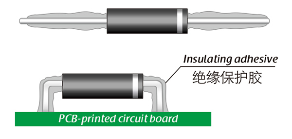
Here, suitable insulation adhesive materials can be selected based on the different usage situations of engineers.