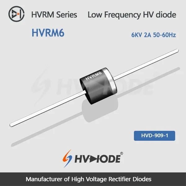
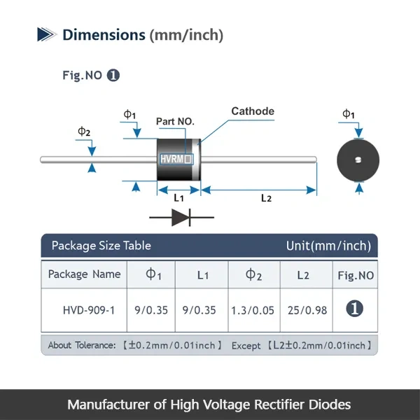
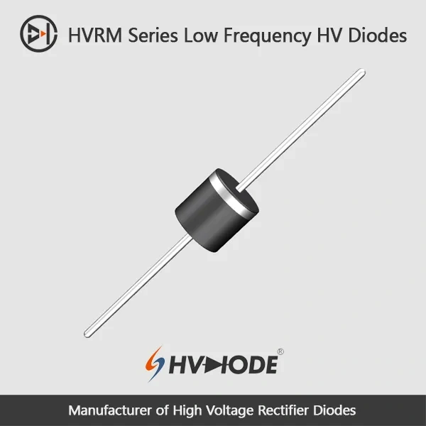
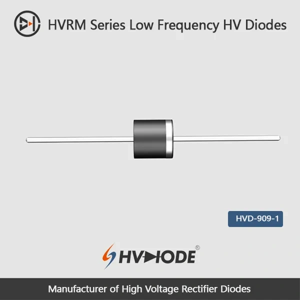
• HVRM6- Low frequency high voltage diode 6KV,2A,50-60Hz
  • HVRM6- Low frequency high voltage diode 6KV,2A,50-60Hz
  • HVRM6- Low frequency high voltage diode 6KV,2A,50-60Hz
  • HVRM6- Low frequency high voltage diode 6KV,2A,50-60Hz
  • HVRM6- Low frequency high voltage diode 6KV,2A,50-60Hz
  • HVRM6- Low frequency high voltage diode 6KV,2A,50-60Hz
  • HVRM6- Low frequency high voltage diode 6KV,2A,50-60Hz
  • HVRM6- Low frequency high voltage diode 6KV,2A,50-60Hz

HVRM6- Low frequency high voltage diode 6KV,2A,50-60Hz

Products Main features:
1、Axial leaded connection.
2、High thermal conductivity epoxy compound molding.
3、Excellent surge current resistance
4、Special high temperature resistant chip
  • HVRM6- Low frequency high voltage diode 6KV,2A,50-60Hz
  • HVRM6- Low frequency high voltage diode 6KV,2A,50-60Hz
  • HVRM6- Low frequency high voltage diode 6KV,2A,50-60Hz
  • HVRM6- Low frequency high voltage diode 6KV,2A,50-60Hz
  • Desciption

  • data sheet

  • Installation Guide

 HVRM6  Low frequency high voltage diode Data Sheet 
 Parameter Symbol Unit Test Conditions Value
 Repetitive Peak Backward Voltage Vrrm KV Ta=25℃  Ir=2.0μA 6
 Peak Working Backward Voltage Vrwm KV Ta=25℃  Ir=2.0μA 6
 Average Forward Current If(AV) A 50Hz Half-sine Wave , Resistance load @Tbreak=50℃ 2
 Backward Recovery Time Trr nS   --
 Surge Forward Current Ifsm A 0.01S @ Half-Sine wave  50Hz 180
 Operating Ambient Temperature Ta ℃   -55~+175
 Storage Temperature Tstg ℃   -55~+150
 Forward Peak Voltage Vfm V   ≥7.2
 Backward Peak  Current Irrm1 μA @ Ta=25℃ VRM=VRRM 2.0
Irrm2 μA @ Ta=100℃ VRM=VRRM 20.0
 Absolute Maximum Ratings & Electrical Characteristics


Surge Margin, Thermal Path and Forward Loss

  • The surge rating is 180 A for a single 0.01 s half-sine pulse. That is the allowance a rectifier needs when a filter or capacitor bank charges at switch-on, or when the line is disturbed for a moment — a transient figure, not extra steady-state capacity to add to the average current.
  • Heat leaves through the moulding. A high thermal conductivity epoxy compound encapsulates the chip, so heat moves away from the junction instead of collecting inside a small body, which is what lets a part this size hold 2 A of average forward current.
  • The die is a high-temperature type, matched to an operating ambient range of -55 °C to +175 °C, so a warm enclosure stays inside the design window.
  • Forward peak voltage is published as ≥ 7.2 V, below the limits quoted for the 7 kV and higher steps of the range, which keeps conduction loss modest for a 6 kV part under a 2 A load.
  • The moulded body is compact, leaving room where several rectifier positions sit close together on one board.

Rectifier Stages Sized for a 2 A Load

Bridge rectifier boards, high-voltage rectifier stages and diode PCB assemblies are the usual homes for this model, together with the rectifying sections of industrial power supplies and high-voltage equipment that run straight off the mains cycle. On those boards the reverse-voltage path and the clearances around it drive the layout, and where several high voltage diodes sit in one assembly, the spacing at high potential is worked out early. Circuits that draw close to 2 A are the ones this rating is sized for. Where the load is lighter, the higher-voltage steps of the same range fit better; where the current demand is greater, this model is no longer the right choice.

Keeping the 2 A Rating Cool in Service

  1. Immersion in insulating oil is the most stable arrangement at these voltages: the oil supports the dielectric barrier around the terminations and carries heat away from the body, which matters more on a 2 A part than on the lower-current steps.
  2. Insulating gas works on the same principle, provided the enclosure maintains the gas quality and pressure the assembly was designed around.
  3. Secondary encapsulation hands part of the thermal job to the surrounding compound, so the compound's own limits have to be weighed alongside the diode's — a trade-off that tightens as the load current rises.
  4. In open air or under forced-air cooling, a small body discharges more readily and sheds heat less effectively; fit insulated electrodes at both ends and leave clearance along the high-voltage path.
  5. Surface coatings behave differently once cured. Silicone stays elastic and absorbs shock from roughly -40 °C to +200 °C, which suits assemblies that cycle hot and cold. Acrylic and urethane cure hard and clear, with urethane the steadier of the two in the cold and the less tolerant of heat. Epoxy-based coatings are opaque and sturdy, with the strongest resistance to moisture, chemicals and wear, plus good dielectric properties. Choose to suit the environment the board will meet.

Maker, Range Coverage and Documentation

  • Anshan Suly Electronics Co., Ltd. has built semiconductor high-voltage rectifier components since 2008 and is one of the high voltage diode manufacturers supplying universities, research institutes and industrial equipment builders under the HVDIODE name from Anshan, China.
  • This 6 kV, 2 A model is one step of a range that runs from 5 kV to 15 kV. Engineers comparing high voltage diodes across that range can move one step at a time: the 5 kV part holds the same 2 A, and the higher-voltage steps trade current away as the blocking voltage rises.
  • A datasheet with the absolute maximum ratings and electrical characteristics travels with the part, together with an installation guide covering mounting and insulation practice. The same documentation structure is kept across the family, so two voltage steps can be compared on equal terms.

FAQ

Q1. How do Vrrm and Vrwm differ on this model?

For this part they describe the same ceiling from two angles. Vrrm is the repetitive peak reverse voltage the diode blocks cycle after cycle in normal operation, while Vrwm is the peak working reverse voltage measured under the same test condition. Both are listed as 6 kV at Ta = 25 °C, so the blocking limit is one number rather than a working figure sitting below a higher peak.

Q2. Will it work on a 60 Hz supply as well as 50 Hz?

Yes. The 50-60 Hz band covers both standard mains frequencies, so the same part serves either supply. For a high voltage diode, the load current and the mounting temperature affect the real margin far more than the few hertz of difference, and the published current ratings are quoted on a 50 Hz half-sine wave.

Q3. What is the 180 A surge rating meant to cover?

Short, single events rather than normal running. It is a 0.01 s half-sine pulse at 50 Hz — the shape of stress a rectifier meets when a filter or capacitor bank charges at switch-on, or when the supply is briefly disturbed. It does not add to the 2 A average forward current; the continuous figure stays the limit during steady operation.

Q4. What forward voltage should I plan for?

The datasheet publishes a forward peak voltage of ≥ 7.2 V for this model, which is the figure to use alongside the 2 A load when estimating conduction loss. The 7 kV and higher steps of the range quote higher limits — 8.5 V and upward — so a 6 kV part gives up less of the design budget to forward drop.

Q5. Which steps of the range carry a 2 A load?

Two: this 6 kV model and the 5 kV one. Above them the range trades current for blocking voltage — 1.5 A from 7 kV to 9 kV, 1.0 A at 10 kV and 11 kV, and 0.8 A from 13 kV to 15 kV. If your circuit's reverse voltage sits comfortably under 6 kV, the 5 kV step gives the same current with a lower ceiling. HVDIODE, one of the high voltage diode manufacturers working in this field, documents each step separately, so the two candidates can be compared on the same terms.

Q6. What temperature range is the diode built for?

Operating ambient runs from -55 °C to +175 °C. Storage is rated a little narrower, -55 °C to +150 °C, and that figure applies while the part is not passing current. The wide operating window matches the high-temperature die used in this model, so equipment that runs warm stays inside the design window rather than pressing against its edge.
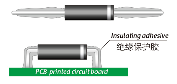
The selection of high-voltage diodes is closely related to their usage environment。

1. Used in insulating oil. (Recommended)
2. Used in insulating gases. (Recommended)
3. Secondary packaging use. (High requirements for heat dissipation and other parameter performance of components)
4. Use in exposed air or add air cooling. (If the size of the high-voltage diode is small, it is easy to discharge, and the heat dissipation performance is average.)

For high-voltage diodes used in exposed air, it is recommended to install them with insulated electrodes at both ends.


Common treatment methods for surface adhesive insulation:

Characteristics of insulation adhesive material:

1. Silicone material usually presents a transparent and elastic rubber state after curing, which is more effective in shock resistance and can also withstand severe stress changes caused by large high and low temperature changes (-40 ° C~200 ° C).

2. Acrylic materials typically exhibit a transparent and hard coating after curing, with low moisture absorption and fast curing time, as well as excellent wear resistance and insulation.

3. After curing, Urethane material usually presents a transparent and hard coating, which has superior wear resistance and good moisture resistance. Its performance is particularly stable in low temperature environments, but it is less resistant to high temperatures.

4. The coating material based on epoxy is very sturdy and usually opaque, with good moisture and moisture resistance. Its resistance to chemical corrosion and wear is also very good. In addition, epoxy also has good dielectric properties.

Here, suitable insulation adhesive materials can be selected based on the different usage situations of engineers.

HVDIODE - Suly Electronics Co., Ltd.

Expects To Provide You With Perfect Service

Name
Email *
Verification Code *
Verification Code
Leave a message
Name
Email *
Message
Verification Code *
Verification Code
We use Cookie to improve your online experience. By continuing browsing this website, we assume you agree our use of Cookie.