| HVRM9 Low frequency high voltage diode Data Sheet | ||||
| Parameter | Symbol | Unit | Test Conditions | Value |
| Repetitive Peak Backward Voltage | Vrrm | KV | Ta=25℃ Ir=2.0μA | 9 |
| Peak Working Backward Voltage | Vrwm | KV | Ta=25℃ Ir=2.0μA | 9 |
| Average Forward Current | If(AV) | A | 50Hz Half-sine Wave , Resistance load @Tbreak=50℃ | 1.5 |
| Backward Recovery Time | Trr | nS | -- | |
| Surge Forward Current | Ifsm | A | 0.01S @ Half-Sine wave 50Hz | 150 |
| Operating Ambient Temperature | Ta | ℃ | -55~+175 | |
| Storage Temperature | Tstg | ℃ | -55~+150 | |
| Forward Peak Voltage | Vfm | V | ≥11 | |
| Backward Peak Current | Irrm1 | μA | @ Ta=25℃ VRM=VRRM | 2.0 |
| Irrm2 | μA | @ Ta=100℃ VRM=VRRM | 20.0 | |
| Absolute Maximum Ratings & Electrical Characteristics | ||||
Functional Targeting for High-Voltage Rectifier Modules
Designed for engineers and procurement specialists in the power electronics sector, this high voltage diode delivers dependable rectification in low-frequency, high-voltage circuits. Its axial leaded connection enhances compatibility with diverse circuit boards, facilitating streamlined installation and replacement in power supply modules. OEMs and industrial users benefit from this diode’s readiness for integration into assemblies requiring stable voltage blocking and forward current conduction. As a product from an experienced high voltage diode manufacture, it addresses operational demands in educational, research, and industrial testing environments, enabling consistent performance under varying conditions.
Technical Features Ensuring Robust Electrical Performance
This diode supports a repetitive peak reverse voltage of 9 kV and an average forward current of 350 mA, with surge capabilities up to 30 A under half-sine wave, 50 Hz conditions. Its construction includes high-thermal-conductivity epoxy molding and a special chip protective glue designed to resist elevated temperatures, enabling operation across a wide ambient range from -40°C to +125°C. Quick-connect terminals and axial leads optimize assembly efficiency and mechanical reliability. These specifications meet stringent requirements expected from high voltage diodes used in demanding rectifier and power supply designs, reflecting the precision and quality assured by focused high voltage diode manufacture.
Industry Applications and Integration Value in Power Electronics
The diode is suited for use within HV power supplies, rectifier modules, and experimental low-frequency high-voltage circuits. It plays a critical role in ensuring voltage breakdown resistance and effective current flow within power conversion systems used by research labs, manufacturing test setups, and industrial automation equipment. The reliable discharge characteristics and temperature tolerance support sustained operation in harsh environments typical of high voltage diode wholsale buyers who require both performance consistency and component longevity. Its design supports system-level integration into assemblies where high voltage diode reliability directly impacts operational safety and efficiency.
Design and Structural Advantages of the High Voltage Diode
The axial leaded configuration combined with quick-connect terminals allows for modular system design and simplified circuit integration, which reduces assembly time for manufacturers and service engineers. The epoxy molding with high thermal conductivity enhances heat dissipation, maintaining device stability under thermal stress. The high-temperature resistant chip protective glue contributes to structural durability, ensuring the diode withstands operational extremes. This level of engineering reflects the advanced design capabilities expected from reputable high voltage diode manufacture, providing users with robust, maintainable components suitable for diverse power electronics configurations.
Performance Benefits and User-Centric Operational Value
By supporting a peak reverse voltage of 9 kV and surge currents up to 30 A, the diode meets the rigorous electrical demands typical in high-voltage rectification applications. Its wide ambient temperature tolerance ensures reliable function across a range of environmental conditions, minimizing downtime and maintenance cycles. The quick-connect terminal design enhances user efficiency through straightforward replacement and system upgrades. Overall, these performance and usability factors deliver sustained operational value to customers sourcing through high voltage diode wholsale channels, particularly those prioritizing longevity and dependable electrical characteristics in critical power conversion roles.
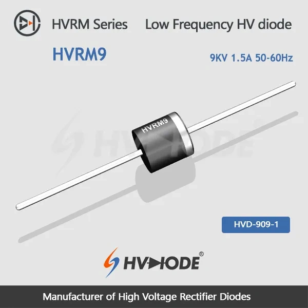
HVRM9 is the 9 KV, 1.5 A member of the HVRM power-frequency family. It sits one step above the 8 KV part and one step below the 10 KV part while keeping the 1.5 A current class, and the data sheet lists 9 KV repetitive peak reverse voltage plus 9 KV peak working reverse voltage, both measured at 25 °C against a 2.0 µA leakage limit. Average forward current is 1.5 A under a 50 Hz half-sine wave into a resistive load at a 50 °C break point, surge capability reaches 150 A for a 0.01 s half-sine pulse, and the part operates from -55 °C to +175 °C. Designs that want more blocking margin than 8 KV without dropping into the 1.0 A tier usually land on this rating.
HVDIODE, the trading name of Anshan Suly Electronics, has built high voltage rectifier components since 2008 for universities, research institutes and industrial customers. High voltage diode manufacturers are judged on consistency, so the plant verifies voltage, current and thermal endurance on test benches and measuring instruments before a batch is released, runs ISO 9001 quality management and holds RoHS and SGS certification for the range. The data sheet and installation guide that match HVRM9 accompany every order, and the technical team stays available for questions on ratings, insulation and mounting after delivery.
Selection support starts before you order. Our technical team reviews your working voltage, forward current, surge and thermal conditions against the published datasheets, then recommends the closest high-voltage diode and confirms the matching part number. We also guide you through installation and insulation considerations, and help troubleshoot issues during qualification or after delivery. Suly Electronics manufactures these diodes directly, supplies them in bulk, and keeps answering technical questions for the parts you already use.
HVRM9 sits between the 8 KV part, which carries the same 1.5 A, and the 10 KV part, which drops to 1.0 A. Choose the 9 KV step when the circuit needs more blocking margin than 8 KV but the average forward current stays within 1.5 A.
It covers a single 0.01 s half-sine pulse at 50 Hz, the shape of stress produced by an inrush current or a transient fault. It is a short-duration capability rather than a continuous overload allowance, so the average forward current must still stay within 1.5 A.
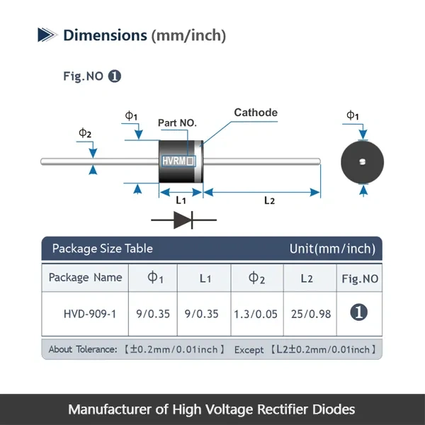
Support the molded body while bending the leads, and keep every bend clear of the epoxy seal so the molding is not stressed or cracked. Use the quick-connect terminals where the layout allows a plug-in connection, and keep the high-voltage surfaces clean, dry and free of flux residue.
Yes. As high voltage diode manufacturers we develop tailored solutions against customer requirements, so if the standard axial-lead body does not fit the assembly, describe the electrical ratings and the mechanical constraints and the R&D team will confirm what is possible.
The epoxy molding has high thermal conductivity, so heat moves away from the junction instead of building up in the package, and it gives the body its mechanical strength. The layer over the chip is formulated to resist high temperature, which keeps the die stable across the -55 °C to +175 °C ambient range and helps the part ride out surge events.
Match the blocking voltage class, the average forward current class, and the mounting and insulation arrangement. Keeping high voltage diodes of the same rating on the shelf means a failed part is replaced with an equivalent rather than triggering a redesign, and the lead and terminal style should be checked against the position before the new diode goes in.
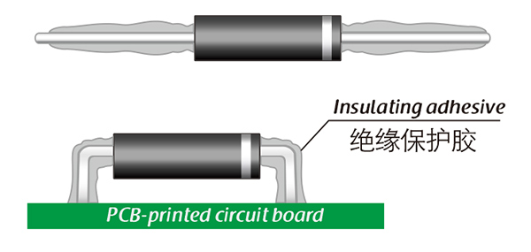
Here, suitable insulation adhesive materials can be selected based on the different usage situations of engineers.