The PC5F is the 100 mA member of the PC Series, a surface-mount range of high voltage diodes built around a 5 kV blocking voltage. Both the repetitive peak reverse voltage and the peak working reverse voltage are rated at 5 kV, quoted at 25 °C with 1.0 µA of reverse current flowing, and the forward drop is published as ≥3.7 V — the lowest floor in the family. Reverse recovery is 75 nS, and a 10 A surge rating sits behind 100 mA of average forward current.
It is built for stages where the voltage is the hard part and the current is small: a multiplier ladder feeding a detector, a focus or bias rail into a high-impedance node, a rectifier block inside a potted module where a few hundred milliwatts of loss would be unwelcome. The body is moulded in a high-thermal-conductivity epoxy, and the terminals are gullwing, bent outward and soldered flat in a reflow pass.
Multiplier ladders are the natural home. A Cockcroft-Walton column for a detector or an image-intensifier supply stacks diodes in series, each one holding off a fraction of the total, and board area per stage is scarce; the small gullwing outline and the 3.7 V drop suit that arithmetic better than a larger part would.
Bias and focus rails are the second case — a few hundred microamps into a high-impedance node, with the diode blocking the full rail voltage for most of the cycle. Clamps and damping positions in high-voltage test gear, and rectifier blocks in non-destructive testing generators and DC high-voltage supplies, behave the same way, provided the average current stays inside 100 mA and the assembly gives the heat somewhere to go.
| Parameter | Test conditions | Value |
|---|---|---|
| Repetitive peak reverse voltage (Vrrm) | Ta = 25 °C, Ir = 1.0 µA | 5 kV |
| Peak working reverse voltage (Vrwm) | Ta = 25 °C, Ir = 1.0 µA | 5 kV |
| Average forward current (If(AV)) | 50 Hz half-sine, resistive load, Tbreak = 50 °C | 100 mA |
| Reverse recovery time (Trr) | — | 75 nS |
| Surge forward current (Ifsm) | 0.01 s half-sine at 50 Hz | 10 A |
| Forward peak voltage (Vfm) | — | ≥3.7 V |
| Reverse leakage at 25 °C (Irrm1) | VRM = VRRM | 1.0 µA |
| Reverse leakage at 100 °C (Irrm2) | VRM = VRRM | 20.0 µA |
| Operating ambient temperature (Ta) | — | -55 to +175 °C |
| Storage temperature (Tstg) | — | -55 to +150 °C |
| Package | Surface mount, gullwing outer bend | — |
| Moulding | High thermal conductivity epoxy compound | — |
| Model | Average forward current | Forward peak voltage | Reverse recovery |
|---|---|---|---|
| PC5F | 100 mA | ≥3.7 V | 75 nS |
| PC5H | 200 mA | ≥4.2 V | 75 nS |
| PC5J | 300 mA | ≥4.3 V | 75 nS |
| PC5N | 500 mA | ≥4.5 V | 75 nS |
| PC5T | 900 mA | ≥5.4 V | 75 nS |
The figures on this product come from the PC5F data sheet, and the same document carries the package drawing and the recommended land pattern. Work from that drawing rather than deriving pads from the body outline: a gullwing joint forms its fillet differently from an inner-bend one, and a pad drawn too short is a common way to end up with a weak joint.
Where a number depends on conditions the sheet does not print, ask. Reverse recovery moves with forward current and di/dt, and forward voltage moves with current and temperature, so the test conditions behind a figure decide whether it applies to your circuit. Send the working voltage, the average current and the ambient your assembly reaches, and the answer comes back from the engineering team at HVDIODE (Suly Electronics Co., Ltd.) against the published ratings. As high voltage diode manufacturers, we publish the complete table for every step in the range rather than a headline figure alone.
Selection starts with your circuit, not a catalogue number: tell us the working voltage, load current, switching frequency and ambient cooling conditions, and our engineers will match a model from our range and explain the margin left in the design. Each model ships with its datasheet, package drawing and installation guide, and we stay available for mounting and soldering questions, start-up checks and fault finding when an existing part runs hot or fails early. Orders run from about 7 days to 6 months depending on quantity, usually by international express.
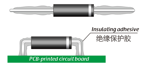
Here, suitable insulation adhesive materials can be selected based on the different usage situations of engineers.