• PC5N SMD high voltage diode 5KV,500mA,75nS
  • PC5N SMD high voltage diode 5KV,500mA,75nS
  • PC5N SMD high voltage diode 5KV,500mA,75nS
  • PC5N SMD high voltage diode 5KV,500mA,75nS
  • PC5N SMD high voltage diode 5KV,500mA,75nS
  • PC5N SMD high voltage diode 5KV,500mA,75nS
  • PC5N SMD high voltage diode 5KV,500mA,75nS
  • PC5N SMD high voltage diode 5KV,500mA,75nS
  • PC5N SMD high voltage diode 5KV,500mA,75nS
  • PC5N SMD high voltage diode 5KV,500mA,75nS

PC5N SMD high voltage diode 5KV,500mA,75nS

Products Main features:
1、SMD connection.
2、High thermal conductivity epoxy compound molding.
3、Fast recovery time for high efficiency.
4、J-Lead(Inner Bend) shapes.
5、Ultra small size package
6、Fast recovery PC Series are the same package size.

The PC5N from HVDIODE is a high-performance surface-mount high voltage diode designed for applications requiring rapid switching and high voltage handling. With a reverse voltage rating of 5KV, a forward current capacity of 500mA, and a swift recovery time of 75nS, this diode ensures efficient performance in demanding high-frequency circuits. Its compact SMD package and superior thermal management make it ideal for industrial, medical, and power supply applications.
  • PC5N SMD high voltage diode 5KV,500mA,75nS
  • PC5N SMD high voltage diode 5KV,500mA,75nS
  • PC5N SMD high voltage diode 5KV,500mA,75nS
  • PC5N SMD high voltage diode 5KV,500mA,75nS
  • PC5N SMD high voltage diode 5KV,500mA,75nS
  • Desciption

  • data sheet

  • SMD HVdiode

  • Installation Guide

Product Overview

The PC5N is a surface-mount high voltage diode rated at 5KV repetitive peak reverse voltage and 500mA average forward current, with a 75nS reverse recovery time. It is built for high-voltage rectifier and multiplier stages where the board is small, the enclosure runs warm, and the part has to keep blocking long after the design has left the bench. It belongs to the PC series, which covers 100mA to 900mA at the same 5KV blocking rating in a single outline — the reason a change of current step late in a project usually does not mean a new board. HVDIODE — Anshan Suly Electronics — is among the high voltage diode manufacturers that supply imaging and industrial power-supply builders, and has been building parts of this kind since 2008. It is specified for the warm case as well as the bench case, so the numbers you design with still mean something after the enclosure has been running for an hour.

SMD high voltage diode PC5N in SMA1-J package

Circuit Role & Rating Fit

Where the part sits. In a high-voltage supply this diode usually does one of three jobs: it rectifies the output of a transformer, it forms one arm of a high voltage bridge rectifier, or it sits inside a multiplier where the reverse voltage adds up stage by stage. The 5KV blocking figure and the 500mA average rating together decide which of those jobs it can take.

Blocking margin. Vrrm and Vrwm are both published as 5KV at Ta = 25 °C and Ir = 1.0 µA. Treat that as the ceiling rather than the working point, and leave room below it — for transients, and for the way a series stack in a multiplier adds voltage across several devices at once.

Forward drop and heat. Vfm is given as ≥4.5V, which is a limit rather than a typical, so size the copper and any potting around the high end of the spread. At 500mA the forward drop is the main source of heat inside the part, and the epoxy molding is what carries it out to the board.

Leakage when the box warms up. Reverse current is 1.0 µA at 25 °C and 20.0 µA at 100 °C, both at VRM = VRRM. On a single rectifier that is a detail; in a stacked multiplier, or on a high-impedance bias rail where every microamp turns into a voltage error, it is the number to check before the design is committed.

Recovery. 75nS puts this part in the fast-recovery class. That is the figure that decides whether it can serve as a high voltage rectifier diode in a switch-mode stage, where the device has to stop conducting before the voltage across it reverses.

Current step and headroom. If your average current sits well below 500mA, the same outline is available at lower current steps with a lower forward drop. If you are already close to 500mA, check the dissipation first — forward voltage climbs as the current step climbs, and so does the heat you have to move.

Thermal Behaviour Above 100 °C

Every leakage figure published for this SMD high voltage diode is measured at the full 5KV: 1.0 µA at 25 °C and 20.0 µA at 100 °C. The pair shows the shape of the curve — reverse current climbs about twentyfold between a cold bench and a warm enclosure — but two points are not a curve, and nothing is published between 100 °C and the +175 °C operating ceiling. A board that soaks hotter than 100 °C therefore sits outside the range you can read straight off the data sheet, and extending the line yourself is guesswork dressed as a calculation. Ask us instead, and put four things in the enquiry: the working reverse voltage, the average and peak load current, the temperature you have actually measured, and how the part is cooled or potted.

The 500mA average forward current has its own temperature footing: it is quoted on a 50 Hz half-sine into a resistive load with the mounting base at Tbreak = 50 °C. A part running with a hotter base cannot be assumed to carry 500mA, however generous the ambient rating looks. Current capability falls as the base temperature rises, and how far it falls depends on the path the heat takes — copper area under the terminals, airflow, potting compound, insulating oil. That is why the cooling arrangement tells us more than a single ambient figure, and why high voltage diode manufacturers quote the current against a base temperature rather than on its own.

Measure the temperature that actually governs the part. Air temperature inside an enclosure says little about a diode dissipating into a board; a thermocouple on the body, or on the copper directly beneath it, taken after the unit has run at full load to steady state, is the number to design to. In a multiplier or a bridge, measure the hottest device rather than the average one.

Then confirm the effect where it will show. Run the supply at maximum working voltage and load, soak it at its real steady-state temperature, and watch the leakage-sensitive node — a bias rail that drifts, a divider that loses accuracy, or a series stack that unbalances. If leakage at soak temperature is already spending your error budget at 100 °C, the answer above that point is a lower working voltage or a different part, not a longer extrapolation. Send us the measured figures and we will say which of the two it is.

Applications

ApplicationWhere the diode sitsWhat matters there
Medical imaging generators — X-ray, DR, CT, dental panoramicRectifier or multiplier stage inside the high-voltage tankBlocking stays stable while the insulating oil warms up
Industrial NDT and DC high-voltage test equipmentMultiplier and rectifier stagesRepeatable recovery under a pulsing load
High voltage bridge rectifier assembliesOne arm of a half or full bridgeForward drop matched across the arms so current shares evenly
High-frequency switch-mode HV suppliesOutput rectifierThe 75nS recovery keeps turn-off loss out of the heat budget
Potted secondary modulesInside an encapsulated high-voltage blockHeat leaving the body through the potting compound
Field repair and replacementDrop-in on an existing boardReplacing high voltage diodes that have failed in service, on the same pads

Installation & Insulation

  1. Start from the package drawing. The SMA1-J outline is dimensioned in mm ±0.1 and inches ±0.004; check it against your land pattern before the first panel is ordered, not after.
  2. Set orientation. The cathode band goes to the silkscreen marking, and every part on the board faces the same way so a later rework does not depend on memory.
  3. Use the published PCB solder-joint layout as your starting pad geometry, then adjust only for the rules your own assembly house applies.
  4. Decide the working medium early. Insulating oil and insulating gas are the recommended environments because the medium closes the insulation path around the body; a potted secondary package and open air each put different demands on the part.
  5. Watch the insulation distance. J-bend terminals tuck under the body, so the creepage path between the poles of this SMD high voltage diode is short — shorter than on the axial high voltage diodes in the 2CL series, where the leads run out past the body and add length to the path. In open air, fill between the poles with an insulating material, apply a three-proof coating, or fit insulated electrodes at both ends.
  6. Reflow with the profile your assembly house has qualified for this package. If the part is new to your line, send us your profile and we will confirm it is sensible for the molding and the terminals.
  7. Clean before coating. Flux residue left on a 5KV surface is a leakage path; wash and dry the assembly before any adhesive or coating goes on.
  8. Inspect under magnification. Look for voids or cold joints under the terminals, where the field will sit in service, and for any crack in the body edge after handling.

Specifications

- 5KV blocking at low reverse current — Vrrm and Vrwm are both 5KV at Ta = 25 °C with reverse current held to 1.0 µA, so the part holds its blocking margin without loading the rail it protects. - 500mA average forward current — quoted on a 50 Hz half-sine, resistive load at Tbreak = 50 °C, which is enough headroom for the rectifier stages of compact imaging and test-equipment supplies. - 75nS recovery — the high voltage rectifier diode returns to blocking quickly after each conduction interval, keeping turn-off loss out of the heat budget in a switch-mode or multiplier stage. - J-bend (inner bend) terminals — the leads fold under the body rather than flaring outwards, so the part stays compact and its terminal geometry is predictable under reflow. - High-thermal-conductivity epoxy molding — the package is part of the heat path, which matters most when the part ends up inside a potted module with no airflow at all. - Cathode band marking — orientation stays readable after soldering, which makes post-assembly inspection and fault-finding on a populated board practical.

ParameterValue and test conditions
Repetitive peak backward voltage (Vrrm)5KV at Ta = 25 °C, Ir = 1.0 µA
Peak working backward voltage (Vrwm)5KV at Ta = 25 °C, Ir = 1.0 µA
Average forward current (If(AV))500mA, 50 Hz half-sine, resistive load, Tbreak = 50 °C
Reverse recovery time (Trr)75nS
Surge forward current (Ifsm)10A, 0.01 s half-sine, 50 Hz
Forward peak voltage (Vfm)≥4.5V
Reverse current at 25 °C (Irrm1)1.0 µA at VRM = VRRM
Reverse current at 100 °C (Irrm2)20.0 µA at VRM = VRRM
Operating ambient temperature (Ta)−55 °C to +175 °C
Storage temperature (Tstg)−55 °C to +150 °C
PackageSMA1-J surface mount, J-bend (inner bend) leads
BodyHigh-thermal-conductivity epoxy molding with cathode band

Insulation Adhesive Materials

  • Silicone — cures to a transparent, elastic rubber. It absorbs shock and rides out the stress of large hot-cold swings, staying usable from roughly −40 °C to 200 °C.
  • Acrylic — cures to a transparent, hard coating with low moisture absorption and a fast cure, combining good wear resistance with good insulation.
  • Urethane — cures hard and transparent, wears well and keeps moisture out, and is particularly stable in cold conditions; it is the least heat tolerant of the four.
  • Epoxy — cures rigid and usually opaque, with strong resistance to moisture, chemicals and wear, plus good dielectric properties.
  • Where it has to go — the fill or coating needs to cover the gap between the two terminals and the body edge, not only the solder joints.
  • What the choice really decides — how much heat can leave the part. Every compound here slows that path to some degree, so on a device running near its 500mA limit choose on thermal conductivity as well as dielectric strength, and check the temperature rise afterwards.

Ordering & Delivery

  1. Ask for the data sheet and the package drawing if you need them for a design file or an incoming-inspection sheet.
  2. If the rail needs more than 5KV, we also supply high voltage diodes in the axial 2CL series from 16KV to 30KV — say what voltage you are working at and we will point you to the right class.
  3. Confirm the quantity and the schedule with your sales contact. Small standard quantities and scheduled production builds are handled differently, and the window typically runs from about a week to several months depending on volume and configuration.
  4. Confirm the payment method and the quantity terms before the order is raised.
  5. Ask about sample availability if you want parts for bench testing or qualification, and we will confirm what is possible for your build.
  6. Shipping is by international express; give us the consignee details and any labelling your customs broker needs.
  7. Parts arrive in blister trays inside a carton, so keep them in that packaging until the board is ready for them.
Kraft boxes and tray with plastic-wrapped diode components

Technical Support & Model Matching

Selection starts with your circuit, not a catalogue number: tell us the working voltage, load current, switching frequency and ambient cooling conditions, and our engineers will match a model from our range and explain the margin left in the design. Each model ships with its datasheet, package drawing and installation guide, and we stay available for mounting and soldering questions, start-up checks and fault finding when an existing part runs hot or fails early. Orders run from about 7 days to 6 months depending on quantity, usually by international express.

FAQ

How do I judge whether 75nS is fast enough for my switching frequency?

Compare it with the switching period rather than with the frequency alone: the recovery time should be a small fraction of the interval during which the diode is meant to be blocking. This part is in the fast-recovery class, which is why it is used as a high voltage rectifier diode in switch-mode and multiplier stages. In 50 Hz power-frequency rectification the same figure barely matters — there the forward drop is the parameter worth optimising.

Can this diode be used in a high voltage bridge rectifier?

Yes. It is a single diode, so it makes one arm of a half or full bridge, and four of them make a full bridge. Match forward drop across the arms as closely as the ≥4.5V spread allows, so current shares evenly instead of loading one device, and remember that in a bridge each diode carries the full reverse voltage when its opposite arm conducts.

What happens if the assembly runs above 100 °C?

Operating ambient temperature is rated to +175 °C, but reverse current is published at only two points, 25 °C and 100 °C, so above 100 °C the leakage keeps climbing without a curve to read it from. If your enclosure sits that high in steady state, send us the working voltage, the load and the expected ambient, and we will advise on the margin rather than leave you to extrapolate.

Can several of these be stacked in series for a higher rail?

They can, and multiplier stages do exactly that. Two things decide whether the stack behaves: budget the reverse voltage across each device so no single diode sits near 5KV, and start from parts with matching forward drop so the voltage divides predictably. Leakage matters more in a stack than in a single rectifier, because the reverse currents add up and unbalance the division.

How much surge current can it survive?

The published surge rating is 10A for a 0.01 s half-sine at 50 Hz. Read it as a single-event capability for inrush and discharge transients, not as a continuous overload allowance — a circuit that pulses repeatedly into the diode has to be checked thermally, because the average current rating is 500mA and the heat has to leave through the molding.

Does the diode need oil or potting, or can it run in open air?

Insulating oil and insulating gas are the recommended environments, because the medium fills the space around the body and closes the insulation path. In open air the high voltage diode still works, but the J-bend terminals leave a short creepage path between the poles: fill between the poles with an insulating material, apply a three-proof coating, or fit insulated electrodes at both ends. Any of those treatments also slows heat leaving the body, so check the temperature rise afterwards.

How do I tell the cathode end, and what should I check before soldering?

Check the band on the body: on this SMD high voltage diode it marks the cathode, and because it stays visible after reflow it is also what you use for post-assembly inspection. Before soldering, confirm the tape orientation matches your pick-and-place program, look for chipped body edges, and make sure the pads match the published solder-joint layout.

Vrrm and Vrwm are both 5KV — which figure do I design to?

On this device they are the same number: 5KV is quoted for both the repetitive peak backward voltage and the peak working backward voltage, at Ta = 25 °C and Ir = 1.0 µA. That means there is no separate, lower working ceiling to design against — 5KV is the figure for both the recurring waveform and the steady state. How much margin you leave below it is your call, and it should cover transients as well as the normal rail.

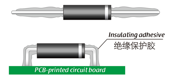
PC series SMD high voltage diodes, due to the design of inner bend angle.

During use, according to the actual working voltage level, it is necessary to pay attention to the insulation distance of the medium.

If it is used completely exposed to the air, it is recommended to fill the two poles with insulating materials, or immerse in three-proof paint, which will achieve more reliable insulation.

Of course, this will also affect the heat dissipation performance of the SMD high voltage diode.

Therefore, according to the temperature rise, there are different solutions for selecting insulating glue with suitable insulation and thermal conductivity.

Of course, this solution is not necessary, you just need to consider this aspect in your design plan.
In most cases, the working medium of insulating oil and insulating gas does not need to consider this kind of solution.
The selection of high-voltage diodes is closely related to their usage environment。

1. Used in insulating oil. (Recommended)
2. Used in insulating gases. (Recommended)
3. Secondary packaging use. (High requirements for heat dissipation and other parameter performance of components)
4. Use in exposed air or add air cooling. (If the size of the high-voltage diode is small, it is easy to discharge, and the heat dissipation performance is average.)

For high-voltage diodes used in exposed air, it is recommended to install them with insulated electrodes at both ends.


Common treatment methods for surface adhesive insulation:

Characteristics of insulation adhesive material:

1. Silicone material usually presents a transparent and elastic rubber state after curing, which is more effective in shock resistance and can also withstand severe stress changes caused by large high and low temperature changes (-40 ° C~200 ° C).

2. Acrylic materials typically exhibit a transparent and hard coating after curing, with low moisture absorption and fast curing time, as well as excellent wear resistance and insulation.

3. After curing, Urethane material usually presents a transparent and hard coating, which has superior wear resistance and good moisture resistance. Its performance is particularly stable in low temperature environments, but it is less resistant to high temperatures.

4. The coating material based on epoxy is very sturdy and usually opaque, with good moisture and moisture resistance. Its resistance to chemical corrosion and wear is also very good. In addition, epoxy also has good dielectric properties.

Here, suitable insulation adhesive materials can be selected based on the different usage situations of engineers.

HVDIODE - Suly Electronics Co., Ltd.

Expects To Provide You With Perfect Service

Name
Email *
Verification Code *
Click to verify
Leave a message
Name
Email *
Message
Verification Code *
Click to verify
We use Cookie to improve your online experience. By continuing browsing this website, we assume you agree our use of Cookie.