The PC5T is the highest-current device in our PC series of surface-mount rectifiers: a 5KV, 900 mA high voltage diode with a 75 nS recovery time, built into the same compact J-lead body as the rest of the family. It is the part we point to when a 500 mA device no longer leaves enough headroom but the board has already been laid out around this outline and there is no room for a larger package. The body is molded in a high-thermal-conductivity epoxy compound, and that is what allows 900 mA of average forward current to be handled in an outline this small. The leads are formed as J-leads that bend inward beneath the body, so the solder joint stays tucked under the package and the finished assembly keeps a low profile on the board. In practice the part replaces either a lower-current SMD diode that has run out of margin or a through-hole diode that took up more board area than the layout could spare. The surrounding circuit - divider strings, current-limiting resistors, feedback - normally carries over unchanged, because the reverse-voltage class is the same as the rest of the series. One trade-off is worth weighing before you commit: at 900 mA the forward voltage is higher than on the lower-current versions, so conduction loss per amp rises with it. The next sections give the numbers and explain how to check them against your own duty cycle.
This diode is built in a J-lead surface-mount body: the terminals bend inward under the package rather than outward and away, so the solder joint tucks under the body and the metal path between the two poles stays as short as the package allows.
Every rating in the PC series shares that outline, which is the practical part for a design team. Moving from a 500 mA step up to the 900 mA one, or back down during re-qualification, does not mean new pads, new stencil apertures or a board respin.
The molding is matte black epoxy, and the top of the body carries a white cathode band and the part number, so orientation can be confirmed after reflow as well as before it. On a component this small, the band and the printed marking are the fastest way to check that the right SMD high voltage diode went onto the board.
The datasheet includes the dimensioned package drawing in millimetres and inches together with the recommended PCB solder joint layout. Build the pads and stencil apertures from that drawing rather than from a general-purpose SMD footprint: oversize pads let the joint spread under the body and can bridge on a tight high-voltage layout.
The clearest fit is an imaging power supply. X-ray, DR, CT and dental panoramic units all need a rectifier stage that holds a few kilovolts and still stays physically small, and a surface-mount outline keeps the rectifier assembly compact and repeatable from board to board.
Industrial high-voltage equipment follows the same pattern: non-destructive testing sets, DC high-voltage generators, HV test transformers and insulation testers, where a 5KV surface-mount rectifier can sit on a compact board instead of on standoffs.
Radar and accelerator power units use the same part where switching speed matters, because it recovers in 75 nS while holding the full 5KV class, and the recovery contribution stays small relative to conduction loss.
In repair work this is what a service team reaches for when a 5KV surface-mount diode has failed and the original part is hard to buy. The rating table is published, so the replacement can be checked against the failed device instead of guessed at.
Development and pre-production builds are the other steady use: a small quantity of one specific rating while a design is being qualified, then repeat orders once it is released. Distributors stock the range for medical and industrial accounts, because holding 100 mA to 900 mA on one footprint keeps a catalogue simple - these are the high voltage diodes their customers ask for by specification rather than by name.
| Parameter | Symbol | Test conditions | Value |
|---|---|---|---|
| Repetitive peak reverse voltage | Vrrm | Ta = 25 °C, Ir = 1.0 µA | 5 KV |
| Peak working reverse voltage | Vrwm | Ta = 25 °C, Ir = 1.0 µA | 5 KV |
| Average forward current | If(AV) | 50 Hz half-sine wave, resistive load, Tbreak = 50 °C | 900 mA |
| Reverse recovery time | Trr | — | 75 nS |
| Surge forward current | Ifsm | 0.01 s half-sine wave, 50 Hz | 10 A |
| Forward peak voltage | Vfm | — | ≥ 5.4 V |
| Reverse leakage current | Irrm1 | Ta = 25 °C, VRM = VRRM | 1.0 µA |
| Reverse leakage current | Irrm2 | Ta = 100 °C, VRM = VRRM | 20.0 µA |
| Operating ambient temperature | Ta | — | -55 to +175 °C |
| Storage temperature | Tstg | — | -55 to +150 °C |
| Package | — | — | Surface-mount, J-lead (inner bend) |
| Outline | — | — | Shared across the PC series |
Selection starts with your circuit, not a catalogue number: tell us the working voltage, load current, switching frequency and ambient cooling conditions, and our engineers will match a model from our range and explain the margin left in the design. Each model ships with its datasheet, package drawing and installation guide, and we stay available for mounting and soldering questions, start-up checks and fault finding when an existing part runs hot or fails early. Orders run from about 7 days to 6 months depending on quantity, usually by international express.
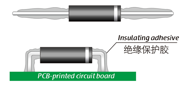
Here, suitable insulation adhesive materials can be selected based on the different usage situations of engineers.