
Categories
  • PF15H SMD high voltage diode 15KV, 200mA, 75nS
  • PF15H SMD high voltage diode 15KV, 200mA, 75nS
  • PF15H SMD high voltage diode 15KV, 200mA, 75nS
  • PF15H SMD high voltage diode 15KV, 200mA, 75nS
  • PF15H SMD high voltage diode 15KV, 200mA, 75nS
  • PF15H SMD high voltage diode 15KV, 200mA, 75nS
  • PF15H SMD high voltage diode 15KV, 200mA, 75nS
  • PF15H SMD high voltage diode 15KV, 200mA, 75nS

PF15H SMD high voltage diode 15KV, 200mA, 75nS

No.PF15H
Products Main features:
1、SMD connection.
2、High thermal conductivity epoxy compound molding.
3、Fast recovery time for high efficiency.
4、Gullwing(Outer Bend) shapes.
5、Ultra small size package
6、Fast recovery PF Series are the same package size.
  • Description

  • data sheet

  • Installation Guide

Product Overview

A compact surface-mount diode for boards that have to hold off kilovolts, this 15 kV high voltage device is built around three numbers: 15 kV repetitive peak reverse voltage at 25 °C with 1.0 µA leakage, 200 mA average forward current with the case held at 50 °C under a 50 Hz half-sine wave into a resistive load, and a 75 ns recovery time. Together they describe the job — stand off kilovolts in the reverse direction, carry a couple of hundred milliamps forward, and return to blocking fast enough that a high-frequency stage does not pay for stored charge on every cycle.

The part earns its place in the middle of the PF fast-recovery family. It gives a designer 15 kV of blocking headroom, which is enough for circuits that would gain nothing from a 20 kV or 25 kV device except a safety factor they cannot use, while keeping the 200 mA current class and the 75 ns recovery the series is built around. Because every model in the family shares one package size, a voltage change later in a project becomes a bill-of-materials change rather than a layout change.

Physically it is a small rectangular surface-mount body with gull-wing leads bent outward. The outer bend leaves the solder fillet visible for inspection and gives the joint a little compliance when the board expands. A white band marks polarity, and the model plus the 15 kV / 200 mA / 75 ns rating are printed on the top face so a fitted part can still be identified after reflow. The body is molded in a high thermal conductivity epoxy compound rather than a general-purpose resin, which is what allows heat to leave through the package and the board instead of sitting inside the junction.

Operating ambient temperature runs from -40 to +175 °C, with storage rated from -40 to +150 °C, so the diode can live close to the warm parts of a supply without being pushed against its ceiling. That ceiling is only half of the thermal story, though. How much current the part can actually carry depends on what surrounds it — insulating oil, insulating gas, potting compound or open air — and that changes the usable margin considerably.

- Surface-mount connection — The diode reflows with the rest of the board, so there is no lead forming, no through-hole drilling and no long unsupported lead end to encourage corona in a high-voltage assembly. - High thermal conductivity epoxy molding — The compound moves heat from the junction into the package surface and the board. Combined with the 50 °C case condition behind the 200 mA rating, it is what keeps the part stable under continuous load. - 75 ns recovery time — Stored charge clears quickly after the forward current falls, so switching losses stay low in high-frequency rectification instead of being burned off as heat on every transition. - Gull-wing (outer bend) leads — The outward bend produces a visible fillet for inspection and absorbs some of the movement between board and package during thermal cycling, which matters in oil-filled or potted assemblies. - Ultra-small package — The footprint is small enough to fit inside a dense high-voltage block rather than forcing the layout to spread around it. - One package across the PF fast-recovery series — The 15 kV, 20 kV and 25 kV parts in this family share a single package size, so stepping between these high voltage diodes leaves the land pattern, stencil and reflow profile untouched. - Ratings published with their conditions — As high voltage diode manufacturers we list Vrrm, If(AV), Trr, Ifsm, forward peak voltage and reverse leakage at both 25 °C and 100 °C, each with the condition it was measured under, so the part can be checked against a circuit before the design is frozen.

Installation Guide

  1. Choose the operating medium before you lay out the board. Insulating oil and insulating gas are the two recommended environments for this part. Potting or secondary encapsulation and open air both work as well, but each asks more of the thermal path and of the voltage clearances.
  2. Oil-immersed assemblies. Mount the diode so the body and both leads sit below the oil line with no trapped air under the package. Oil carries heat away efficiently and suppresses discharge, which makes it the easiest medium to design for.
  3. Insulating gas. Gas gives good dielectric strength without liquid handling, but convection is weaker than in oil. Keep the leads short, avoid sharp points close to the body, and check the current margin against the gas density your enclosure actually maintains.
  4. Secondary encapsulation. A potting compound adds a dielectric layer that also traps heat, so the current figure needs re-checking rather than assuming. Verify temperature rise on a sample assembly before the process is released to production.
  5. Open air. Exposed air is the hardest case. A diode this small is prone to discharge at the lead ends, and heat leaves only through the board, so add air cooling for continuous loads, keep the creepage path clean and dry, and mount with insulated electrodes at both ends.
  6. Board preparation. Lay out the land pattern from the package drawing, keep the polarity band orientation consistent so every fast recovery rectifier on the assembly is fitted the same way, and leave the marked face visible after reflow for identification.
  7. Soldering. Reflow with your standard profile for a small epoxy-bodied surface-mount diode. Avoid prolonged hand-soldering heat on the leads, and never let flux residue bridge the two terminals — at these voltages a residue path behaves like a resistor.
  8. Post-assembly verification. Check reverse leakage at 25 °C, confirm recovery behaviour on a sample, and measure temperature rise under the real load in the real medium at the highest ambient the enclosure will see.

Applications

  • Medical imaging power supplies — Rectifier stages in X-ray and DR generators, where a 15 kV blocking rating with 75 ns recovery keeps the multiplier efficient while the small package keeps the high-voltage block compact.
  • Industrial NDT generators — Portable and cabinet X-ray sets for weld, casting and pipeline inspection, often built in modest volumes where a surface-mount diode simplifies the high-voltage section.
  • High-voltage test equipment — Hipot testers, insulation resistance sets and cable test systems, where the rectifier holds off the full test voltage and has to recover cleanly between pulses.
  • HVDC and electrostatic supplies — Charging and output rectification in high-voltage DC sources, electrostatic circuits and capacitor-charging stages.
  • Radar and pulsed supplies — Modulator and pulse-forming networks that need a fast recovery rectifier at high voltage so the pulse edge stays sharp and losses stay contained.
  • Replacement and second-source work — Teams evaluating high voltage diode manufacturers for an existing design can compare this part's ratings, package and body marking against the device already fitted before committing to a change.

Specifications

ParameterValue
Part numberPF15H
Repetitive peak reverse voltage (Vrrm)15 kV at Ta = 25 °C, Ir = 1.0 µA
Peak working reverse voltage (Vrwm)15 kV at Ta = 25 °C, Ir = 1.0 µA
Average forward current (If(AV))200 mA, 50 Hz half-sine wave, resistive load, Tbreak = 50 °C
Recovery time (Trr)75 ns
Surge forward current (Ifsm)10 A, 0.01 s half-sine wave at 50 Hz
Forward peak voltage (Vfm)≥15.5 V
Reverse leakage at 25 °C (Irrm1)1.0 µA at VRM = VRRM
Reverse leakage at 100 °C (Irrm2)20.0 µA at VRM = VRRM
Operating ambient temperature (Ta)-40 to +175 °C
Storage temperature (Tstg)-40 to +150 °C
PackageSurface mount, gull-wing (outer bend) leads
Molding compoundHigh thermal conductivity epoxy

Insulation Adhesive Selection

Where the assembly is potted, coated or encapsulated, the insulation adhesive becomes part of the electrical design rather than a cosmetic layer. Four adhesive families are commonly used around a mounted high voltage fast recovery rectifier, and each cures into a different surface with its own balance of shock resistance, moisture protection and temperature tolerance.

Silicone cures to a transparent, elastic rubber. It takes shock and mechanical stress well, and it tolerates the large expansion and contraction of wide temperature swings — roughly -40 °C to 200 °C — which makes it the natural choice where the assembly will cycle hard or vibrate.

Acrylic cures to a transparent, hard coating with low moisture absorption, a fast cure and strong wear and insulation performance. It suits a line that needs the assembly handleable quickly and a surface that stays dimensionally stable.

Urethane also cures hard and clear, with better wear resistance than acrylic and good moisture resistance. It stays particularly stable at low temperature but is less tolerant of high temperature, so it belongs on the cooler side of a design rather than next to a heat source.

Epoxy is the toughest of the four: usually opaque, mechanically strong, resistant to moisture, chemical attack and wear, with good dielectric properties. Where the assembly needs physical protection as much as insulation, epoxy is the default.

Because each family trades one property for another, the choice follows the working conditions — operating temperature, whether the part sits in oil or air, how much mechanical stress the joint will see, and how much heat the coating has to pass. Tell us the medium and the surrounding components and we will point you to the family that fits; if you already have a qualified compound, we will confirm that the diode's dimensions and mounting guidance work with it.

Ordering & Delivery

  1. Send the model and the quantity. Quote the model number printed on the body, or send the line from your bill of materials together with your per-release and annual quantities.
  2. Confirm the commercial terms with your sales contact. Price, minimum order quantity and lead time are quoted per order and depend on quantity and schedule, so they are confirmed in writing at quotation stage rather than fixed in advance. Ask about sample availability if you need parts for bench evaluation.
  3. Documentation travels with the quotation. Buyers comparing high voltage diode manufacturers usually want the ratings table, the package drawing and the installation guide before they raise a purchase order, so all three are issued with the offer and the engineering and purchasing approvals can run in parallel.
  4. Shipping. Orders are dispatched by international express.

Technical Support & Model Matching

Selection starts with your circuit, not a catalogue number: tell us the working voltage, load current, switching frequency and ambient cooling conditions, and our engineers will match a model from our range and explain the margin left in the design. Each model ships with its datasheet, package drawing and installation guide, and we stay available for mounting and soldering questions, start-up checks and fault finding when an existing part runs hot or fails early. Orders run from about 7 days to 6 months depending on quantity, usually by international express.
FAQ

What does the 15 kV rating actually cover?

Both the repetitive peak reverse voltage and the peak working reverse voltage are 15 kV, measured at 25 °C with 1.0 µA of reverse leakage. That is the steady-state blocking figure. Transients are covered separately by a 10 A surge rating for a 0.01 s half-sine pulse at 50 Hz, so a circuit that expects repeated spikes should still leave usable margin below 15 kV rather than designing right up to it.

Can the diode carry 200 mA continuously?

200 mA is the average forward current with the case held at 50 °C, measured on a 50 Hz half-sine wave into a resistive load. Whether that holds in your assembly depends on the heat path, since oil removes heat far better than still air. Check temperature rise in the real medium before releasing the design, and derate where the ambient sits near the top of the -40 to +175 °C range.

Does this high voltage diode need a heatsink?

There is no heatsink to bolt on. Heat leaves through the package, the board and the surrounding medium: in oil or a potted block the thermal path is good, while in still air it is limited and that is where forced air or a copper area under the leads makes the difference. The -40 to +175 °C ambient range tells you how hot the environment may be, not how much current the part can shed there.

Is it interchangeable with other models in the PF series?

Mechanically yes. Every model in the family shares one package size, so the land pattern, stencil and reflow profile carry over. Electrically no: the 15 kV, 20 kV and 25 kV parts block different voltages, so high voltage diodes from the same family cannot be swapped up or down without rechecking the circuit's margin. Match the marking on the body against the bill of materials before fitting.

What forward voltage should I design for?

The ratings table gives forward peak voltage as at least 15.5 V, so treat 15.5 V as the floor rather than a typical value when you calculate conduction loss at the rated current. Compare it against the measured value on your own sample at the operating temperature you expect, because the figure moves with temperature.

The selection of high-voltage diodes is closely related to their usage environment。

1. Used in insulating oil. (Recommended)
2. Used in insulating gases. (Recommended)
3. Secondary packaging use. (High requirements for heat dissipation and other parameter performance of components)
4. Use in exposed air or add air cooling. (If the size of the high-voltage diode is small, it is easy to discharge, and the heat dissipation performance is average.)

For high-voltage diodes used in exposed air, it is recommended to install them with insulated electrodes at both ends.


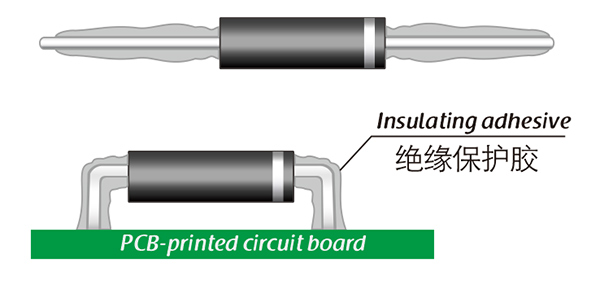
Common treatment methods for surface adhesive insulation:

Characteristics of insulation adhesive material:

1. Silicone material usually presents a transparent and elastic rubber state after curing, which is more effective in shock resistance and can also withstand severe stress changes caused by large high and low temperature changes (-40 ° C~200 ° C).

2. Acrylic materials typically exhibit a transparent and hard coating after curing, with low moisture absorption and fast curing time, as well as excellent wear resistance and insulation.

3. After curing, Urethane material usually presents a transparent and hard coating, which has superior wear resistance and good moisture resistance. Its performance is particularly stable in low temperature environments, but it is less resistant to high temperatures.

4. The coating material based on epoxy is very sturdy and usually opaque, with good moisture and moisture resistance. Its resistance to chemical corrosion and wear is also very good. In addition, epoxy also has good dielectric properties.

Here, suitable insulation adhesive materials can be selected based on the different usage situations of engineers.

  • PF15H SMD high voltage diode 15KV, 200mA, 75nS
  • PF15H SMD high voltage diode 15KV, 200mA, 75nS
  • PF15H SMD high voltage diode 15KV, 200mA, 75nS
  • PF15H SMD high voltage diode 15KV, 200mA, 75nS
Leave a message
Name
Email *
Message
Verification Code *
Click to verify
We use Cookie to improve your online experience. By continuing browsing this website, we assume you agree our use of Cookie.