
Your products's number


The PF20H is a surface-mount high voltage diode built for rectification inside compact high-voltage supplies. The body is a small black epoxy molding with gullwing leads that bend outward and sit flat on the pads; a white stripe marks the polarity and the body carries its marking so the part can be checked before the board goes through reflow. Against an axial-lead diode from other high voltage diode manufacturers, it saves the drilling and the hand-soldering and takes a fraction of the board area. Against a low-voltage rectifier it asks for more care: at this voltage the insulation around the part, not the part itself, usually sets the limit, which is why the installation and coating guidance on this product matters as much as the ratings do. - Surface-mount gullwing terminals — the leads bend outward so they rest flat on the pads and form a fillet you can inspect; the shape spreads mechanical and thermal stress away from the body edge instead of concentrating it there. - High thermal conductivity epoxy molding — heat leaves the junction through the molding into the leads and the board, which is what keeps a body this small workable inside an enclosed supply where convection does little. - One package across the PF range — the PF fast-recovery high voltage diodes are built on the same package size, so moving to another voltage or current rating does not force a new land pattern on your board. - Wide operating ambient range — from -40 °C to +175 °C, covering cold-start equipment as well as oil-immersed assemblies that settle at a high running temperature. - Reverse leakage published cold and hot — leakage is specified at both 25 °C and 100 °C, so the hot behaviour of the part is visible before you commit a design rather than something you only learn on the test bench. - Surge rating of 10 A — the part is rated for a 0.01 s half-sine surge, which covers short inrush and flashover events that a rectifier sees in high-voltage equipment.
| Parameter | Test conditions | Value |
|---|---|---|
| Repetitive peak reverse voltage (Vrrm) | Ta = 25 °C, Ir = 1.0 µA | 20 kV |
| Peak working reverse voltage (Vrwm) | Ta = 25 °C, Ir = 1.0 µA | 20 kV |
| Average forward current (If(AV)) | 50 Hz half-sine, resistive load, Tbreak = 50 °C | 200 mA |
| Reverse recovery time (Trr) | — | 75 ns |
| Surge forward current (Ifsm) | 0.01 s half-sine, 50 Hz | 10 A |
| Forward peak voltage (Vfm) | — | ≥15.7 V |
| Reverse leakage (Irrm1) | Ta = 25 °C, VRM = VRRM | 1.0 µA |
| Reverse leakage (Irrm2) | Ta = 100 °C, VRM = VRRM | 20.0 µA |
| Operating ambient temperature (Ta) | — | -40 to +175 °C |
| Storage temperature (Tstg) | — | -40 to +150 °C |
| Package | — | SMD, gullwing (outer bend) leads |
| Molding compound | — | High thermal conductivity epoxy |
A figure only means something together with the condition it was measured at, so the data sheet rows are worth reading as a set. The average forward current is quoted for a 50 Hz half-sine wave into a resistive load with a break temperature of 50 °C. Change the waveform, the load or the break temperature and the safe current changes with it: a board that settles hotter than that must be derated, and a pulsed or capacitive load is harder on the part than a resistive one.
The blocking figures are taken at 25 °C. Leakage current is temperature dependent, and the second leakage row at 100 °C exists precisely so that you can see how far it moves — a hot leakage or hipot reading that comes back higher than the cold one is expected behaviour, and it should be judged at the temperature the board really reaches, not at the bench.
The temperature rows deserve a second look. Storage has its own, lower ceiling than the operating range, so check that row before parts sit in a drying oven, a hot vehicle or a summer container on the way to your line.
The surge rating is tied to a defined pulse: a 0.01 s half-sine at 50 Hz. It describes a short, shaped transient and does not extend to repetitive overcurrent or to a sustained fault, so protect the rectifier as your topology requires.
Datasheets from different high voltage diode manufacturers only compare fairly when the test conditions behind the numbers match, which is why every value here is printed with its condition beside it.
| Material | Property | Detail |
| Silicone | Cured state | Transparent, elastic rubber that stays flexible |
| Silicone | Strengths | Absorbs shock and rides out severe hot/cold cycling, roughly -40 °C to 200 °C |
| Acrylic | Cured state | Transparent, hard coating |
| Acrylic | Strengths | Low moisture absorption, fast cure, good wear resistance and insulation |
| Urethane | Cured state | Transparent, hard coating |
| Urethane | Strengths | Wear and moisture resistance with stable behaviour at low temperature; less tolerant of heat than silicone |
| Epoxy | Cured state | Very tough and usually opaque |
| Epoxy | Strengths | Moisture, chemical and wear resistance with good dielectric properties |
Selection starts with your circuit, not a catalogue number: tell us the working voltage, load current, switching frequency and ambient cooling conditions, and our engineers will match a model from our range and explain the margin left in the design. Each model ships with its datasheet, package drawing and installation guide, and we stay available for mounting and soldering questions, start-up checks and fault finding when an existing part runs hot or fails early. Orders run from about 7 days to 6 months depending on quantity, usually by international express.
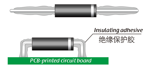
Here, suitable insulation adhesive materials can be selected based on the different usage situations of engineers.


