
Categories
  • PF20J SMD high voltage diode 20KV, 300mA, 75nS
  • PF20J SMD high voltage diode 20KV, 300mA, 75nS
  • PF20J SMD high voltage diode 20KV, 300mA, 75nS
  • PF20J SMD high voltage diode 20KV, 300mA, 75nS
  • PF20J SMD high voltage diode 20KV, 300mA, 75nS
  • PF20J SMD high voltage diode 20KV, 300mA, 75nS
  • PF20J SMD high voltage diode 20KV, 300mA, 75nS
  • PF20J SMD high voltage diode 20KV, 300mA, 75nS

PF20J SMD high voltage diode 20KV, 300mA, 75nS

Products Main features:
1、SMD connection.
2、High thermal conductivity epoxy compound molding.
3、Fast recovery time for high efficiency.
4、Gullwing(Outer Bend) shapes.
5、Ultra small size package
6、Fast recovery PF Series are the same package size.
  • Description

  • data sheet

  • Installation Guide

20 kV Blocking in a Gullwing SMD Package

The PF20J is the 20 kV, 300 mA member of the PF surface-mount high voltage diode family. The body is a moulded epoxy package with leads bent outward into a gullwing shape, so the part sits flat on the pads and leaves a fillet that can be inspected from the side after reflow. Average forward current is 300 mA on a 50 Hz half-sine wave into a resistive load with the break temperature at 50 °C — the highest current rating the PF line offers at 20 kV. Leakage is the figure that moves with heat. At 25 °C the diode holds 1.0 µA at rated reverse voltage, and at 100 °C the same measurement reads 20.0 µA. That rise is normal for a silicon rectifier and it is why the insulation and spacing around the part are usually set from the warm figure rather than from a bench reading.

PF20J Beside the 20 kV and 15 kV PF Models

The three share one package size, so the choice is electrical rather than mechanical: PF20J gives 100 mA more forward current than PF20H at the same 20 kV, and PF15H trades 5 kV of blocking margin for a smaller reverse overdesign when the supply settles below 15 kV.

ModelVrrmIf(AV)TrrOperating ambientForward peak voltage
PF20J20 kV300 mA75 ns-40 to +175 °C≥15.6 V
PF20H20 kV200 mA75 ns-40 to +175 °C≥15.7 V
PF15H15 kV200 mA75 ns-40 to +175 °C≥15.5 V

What 75 ns Recovery Changes at the Switching Node

  • 75 ns reverse recovery — the diode is back in its blocking state within 75 ns of the current crossing zero, so the reverse-current tail that heats both the rectifier and the switch in a high-frequency supply stays short. - Lower loss per transition — the energy dumped at each switching event falls with recovery time, which shows up as a cooler board and better conversion efficiency at the same output. - 10 A surge rating — 0.01 s at 50 Hz half-sine. Start-up inrush into a capacitor bank and the current behind a flashover sit against this number, not against the 300 mA average. - Forward peak voltage of ≥15.6 V — the price of blocking 20 kV in a body this small. In a multiplier or a stacked string, add it up stage by stage before the turns ratio is fixed. Publishing the condition beside the number is what makes a datasheet reproducible, and it is the first point high voltage diode manufacturers are asked to confirm when a design goes through qualification.

What the Surrounding Medium Changes

  1. Insulating oil — the most forgiving arrangement. Oil carries heat away from the body and suppresses discharge at the terminals, so the 20 kV hold-off is easiest to keep and the 175 °C ambient ceiling stays far away.
  2. Insulating gas — clean, dry gas works where oil is impractical, but the terminals need generous clearance so partial discharge does not start at the working voltage.
  3. Potted or encapsulated module — the compound becomes the only thermal path out of the body, so it has to be a dielectric and a heat conductor at the same time.
  4. Open air — the least forgiving option. Mounted in open air, high voltage diodes discharge more readily at their terminals and shed heat only by convection and through the copper they sit on, so keep the surfaces clean and dry.
  5. Insulated electrodes at both ends — route the connections so the field does not concentrate on a sharp edge, and position the part where the terminals are not the closest metal to a grounded surface.

PF20J Ratings and Test Conditions

ParameterSymbolValueTest condition
Repetitive peak reverse voltageVrrm20 kVTa = 25 °C, Ir = 1.0 µA
Peak working reverse voltageVrwm20 kVTa = 25 °C, Ir = 1.0 µA
Average forward currentIf(AV)300 mA50 Hz half-sine wave, resistive load, Tbreak = 50 °C
Reverse recovery timeTrr75 ns—
Surge forward currentIfsm10 A0.01 s, 50 Hz half-sine wave
Forward peak voltageVfm≥15.6 V—
Reverse leakage at 25 °CIrrm11.0 µAVRM = VRRM
Reverse leakage at 100 °CIrrm220.0 µAVRM = VRRM
Operating ambient temperatureTa-40 to +175 °C—
Storage temperatureTstg-40 to +150 °C—
Package—SMD, gullwing (outer bend) leads, epoxy moulded body—

Insulating Compounds and Their Trade-offs

  • Silicone — cures to a clear, elastic rubber with good shock absorption and stays flexible across roughly -40 to +200 °C, which suits assemblies that cycle repeatedly in temperature.
  • Acrylic — a clear, hard coating with low moisture absorption and a fast cure, giving good wear resistance and dielectric strength where a rigid layer is acceptable.
  • Urethane — also clear and hard, with strong wear resistance and good moisture protection; it performs well at low temperature but is the weaker option under sustained heat.
  • Epoxy — the toughest of the four, with good resistance to moisture, chemicals and wear plus solid dielectric properties. It is usually opaque, so the joint underneath cannot be inspected once cured.
  • Matching compound to assembly — silicone where movement and thermal cycling dominate, acrylic or urethane where a thin hard moisture barrier is enough, epoxy where mechanical and chemical protection outweigh the loss of inspection access. A board carrying several high voltage diodes often needs the same compound to serve spots with very different heat loads.

Ordering, Packing and Delivery

  • Shipping — orders are dispatched by international express.
  • Quantity and price — send the model, the build quantity and your target schedule, and we will quote against it.
  • Lead time — confirmed with your sales contact when the order is placed; it depends on the quantity and on stock at that moment.
  • Packing — tell us the format your placement equipment needs and we will confirm what is available.
  • Documentation — datasheet, ratings and package drawing go out with the quotation; ask for the installation guide if a process review needs it.
  • Replacement orders — send the marking on the old diode together with the working voltage and current, and we will check the match before you commit.
  • Supply — as high voltage diode manufacturers we quote both prototype builds and repeat production releases on the same model, so one part can carry a design from first article through to series.

Technical Support & Model Matching

Selection starts with your circuit, not a catalogue number: tell us the working voltage, load current, switching frequency and ambient cooling conditions, and our engineers will match a model from our range and explain the margin left in the design. Each model ships with its datasheet, package drawing and installation guide, and we stay available for mounting and soldering questions, start-up checks and fault finding when an existing part runs hot or fails early. Orders run from about 7 days to 6 months depending on quantity, usually by international express.

The moulding compound does two jobs at once: it is the dielectric around the die and the thermal path out of it, which is why the epoxy is selected for thermal conductivity as well as breakdown strength. Leads are formed outward so both fillets can be seen after reflow, and the flat body self-centres during placement instead of drifting on the paste. Production follows eco-conscious processes, and the environmental case for the part is mostly made in use rather than printed on a label: 75 ns recovery keeps switching loss low for the whole service life, so a supply built around it needs less cooling and runs cooler inside its enclosure. That matters on a high-voltage board, where a few degrees of self-heating also shift the leakage the spacing was calculated around. Each order travels with the datasheet, the package drawing and the installation guide, and every rating on the datasheet is printed with the condition it was measured under. That paper trail is what high voltage diode manufacturers are judged on during a supplier qualification, well before commercial terms come into the conversation.
FAQ

How much margin should the working voltage leave below 20 kV?

Treat 20 kV as the ceiling of the blocking window, not an everyday operating level. Repetitive peak reverse voltage and peak working reverse voltage are both quoted at 20 kV at 25 °C with reverse current at 1.0 µA, so whatever margin you keep below that figure has to absorb switching transients and surges on the input. Clearance and creepage around this high voltage diode belong in the same calculation, because the body only blocks what the board and the potting allow.

What happens to the part when the assembly runs hot?

Leakage climbs: 1.0 µA at rated reverse voltage at 25 °C, 20.0 µA at 100 °C. The warm figure is the one that sizes insulation and spacing in a sealed cabinet, an uncooled oil tank or a potted module. In those builds high voltage diodes sit at the temperature of the medium around them, so read temperature at the body rather than at the cabinet wall when you check the design.

Why does the forward peak voltage matter in a stacked rectifier?

Because it accumulates. Forward peak voltage is specified at ≥15.6 V, and every stage in a multiplier or a series string adds its own drop to the total. Budget the conduction loss across the whole string before the transformer ratio is fixed, and confirm the drop at your operating current rather than assuming a typical value.

Can a board laid out for the PF20H take the PF20J instead?

Yes for the footprint — the PF series shares one package size, so the land pattern and gullwing pads carry over. What changes is electrical: PF20J is rated 300 mA average forward current against 200 mA for PF20H at the same 20 kV, with a forward peak voltage of ≥15.6 V rather than ≥15.7 V. Re-check the thermal budget and the clearance around the terminals before releasing the substitution.

How do the operating and storage limits differ?

Operating ambient is -40 to +175 °C and storage is -40 to +150 °C, so the part may run hotter than it may be stored. Keep warehouse and transit conditions inside the storage window. The 175 °C figure refers to the ambient immediately around the component, which in a densely packed assembly can be well above what a cabinet sensor reads.

The selection of high-voltage diodes is closely related to their usage environment。

1. Used in insulating oil. (Recommended)
2. Used in insulating gases. (Recommended)
3. Secondary packaging use. (High requirements for heat dissipation and other parameter performance of components)
4. Use in exposed air or add air cooling. (If the size of the high-voltage diode is small, it is easy to discharge, and the heat dissipation performance is average.)

For high-voltage diodes used in exposed air, it is recommended to install them with insulated electrodes at both ends.


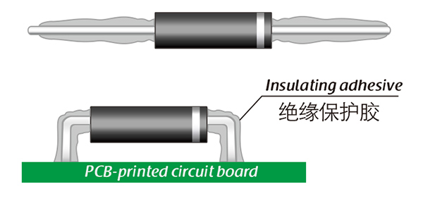
Common treatment methods for surface adhesive insulation:

Characteristics of insulation adhesive material:

1. Silicone material usually presents a transparent and elastic rubber state after curing, which is more effective in shock resistance and can also withstand severe stress changes caused by large high and low temperature changes (-40 ° C~200 ° C).

2. Acrylic materials typically exhibit a transparent and hard coating after curing, with low moisture absorption and fast curing time, as well as excellent wear resistance and insulation.

3. After curing, Urethane material usually presents a transparent and hard coating, which has superior wear resistance and good moisture resistance. Its performance is particularly stable in low temperature environments, but it is less resistant to high temperatures.

4. The coating material based on epoxy is very sturdy and usually opaque, with good moisture and moisture resistance. Its resistance to chemical corrosion and wear is also very good. In addition, epoxy also has good dielectric properties.

Here, suitable insulation adhesive materials can be selected based on the different usage situations of engineers.

  • PF20J SMD high voltage diode 20KV, 300mA, 75nS
  • PF20J SMD high voltage diode 20KV, 300mA, 75nS
  • PF20J SMD high voltage diode 20KV, 300mA, 75nS
  • PF20J SMD high voltage diode 20KV, 300mA, 75nS
Leave a message
Name
Email *
Message
Verification Code *
Click to verify
We use Cookie to improve your online experience. By continuing browsing this website, we assume you agree our use of Cookie.